Getting Started 2–3
Alarm, Temp/RH Connector
The Alarm, Temp/RH Connector is NOT used on these products. There is
an alarm output that comes from external wiring (see Appendix A), and
that will be described in the External Electrical Connections Section of
this manual.
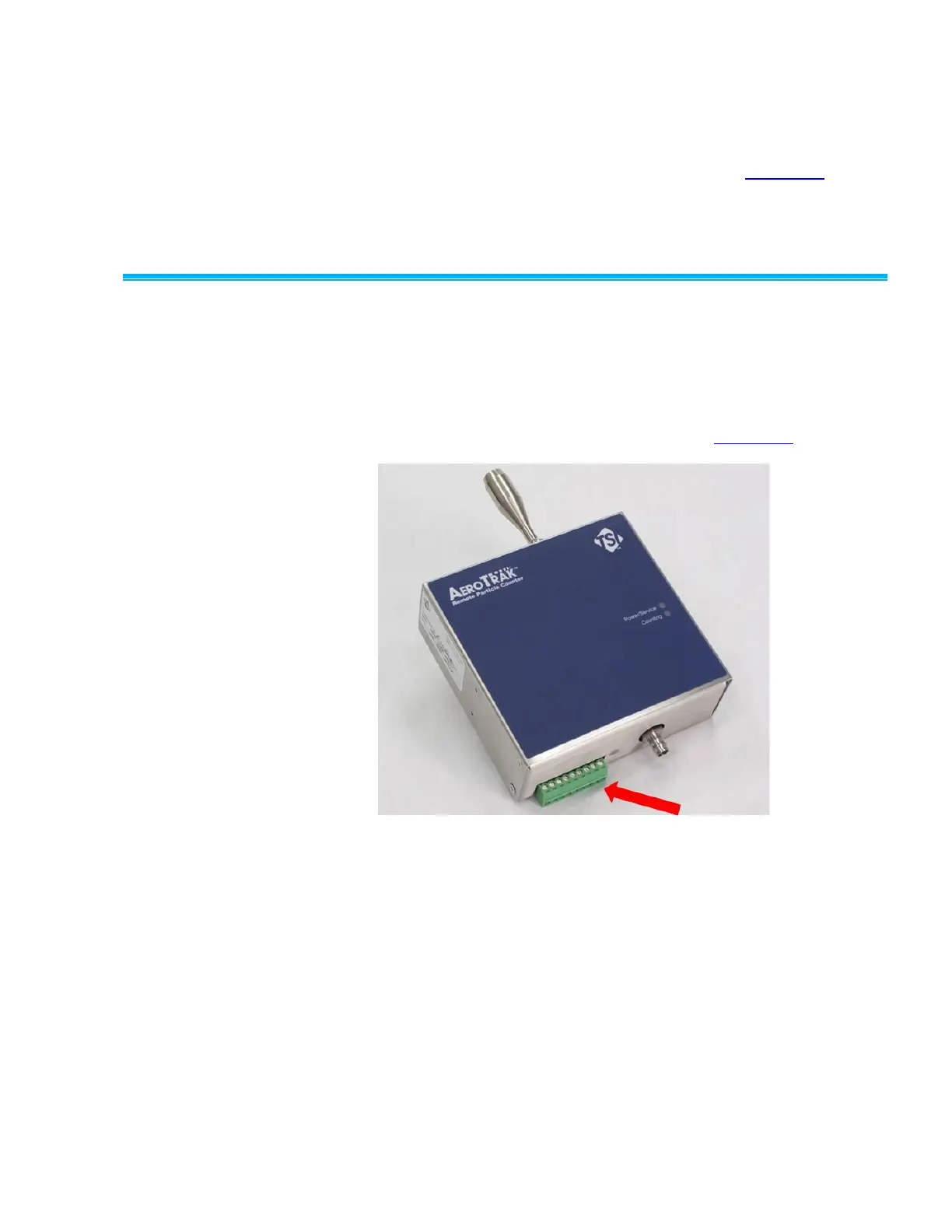
Externa l Ele c t r ical Conne c tions
The AeroTrak Remote Particle Counters with Analog Outputs have a
number of external electrical connections that are used to power the
product and to communicate with external devices like PLCs. These
connections are wired into a separate wiring harness male connector (PN
700120) that can then be inserted into the female connecter on the
particle counter. See complete wiring diagram in Appendix A.
Power: Terminals 8–9
To supply DC power to the particle counter:
1. Use a regulated, clean 24 VDC power source, with enough amperage
to power all of the particle counters that will be connected in the
circuit. Good practices would indicate allowing for future expansion of
the system and voltage loss from extended cabling distances.
2. Connect the 24 VDC power wires to the connector on the particle
counter, using the pin-out diagram provided. The +24 VDC wire
should be connected to Pin 9. The 24 VDC GND should be
connected to Pin 8.
Note: OBSERVE POLARITY. Cross connection or shorting
between the pins could result in permanent damage.
 Loading...