Chapter 2
10
Connecting Analog/Alarm Output
The Analog/Alarm Output Cable plugs into the alarm connection on the side
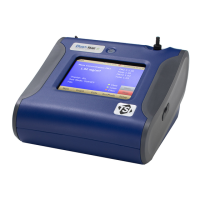
of the instrument. This feature is on the desktop models (II, II HC and 8533)
only.
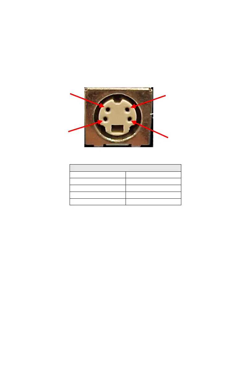
The cable contains a 4-pin, mini-DIN connector. The pin-outs for the
connector and the wiring for the cable are shown below.
4-pin miniDIN connector
Brown Wire Analog Ground
Orange Wire Analog Out
Red Wire Alarm (+)
White Wire Alarm (-)
Black Wire Shield
Figure 2-4: Cable Wiring Diagram
Wiring the Analog Output
• Output voltage: 0 to 5 VDC.
• Output impedance: 0.01 ohm.
• Maximum output current: 15 mA.
• Correct polarity must be observed (see pin-outs above).
The output cable supplied by TSI (part no. 801652) is labeled with the pin-
out wiring diagram. Additional equipment may be needed for making
connections to the system that TSI does not supply. It is the user’s
responsibility to specify and supply all additional equipment.
(+)
Alarm Ground
–
Analog Output
(
)

 Loading...