User’s Manual UDP6900 Series Digital Control Power Supply
Instruments.uni-trend.com 34 / 44
Left Figure Right Figure
Notes:
1. To ensure the stability of the system, please use armored twisted pair cable between the remote
measurement of UDP6900 and the load. Please pay attention to the positive and negative polarity
when connecting the cable, otherwise the instrument will be damaged!
2. The left figure "+" and the right figure "-" are the auxiliary output terminals, the current shall not be
greater than 3A, if you need to output high current, please connect the high current output terminal
on the right figure.
3.15.3 External Analog Quantity
All UDP6900 series has external analog function. There is an external analog interface on the rear panel of
the power supply, it can control the output voltage, current and switching output by inputting an external
voltage (0~10 V), and output monitor by outputting 0~10 V through Vm and Im. If the user connects a voltage
control device to multiple power supplies, the outputs of multiple power supplies can be adjusted at the
same time.
To control or monitor the output of the power supply through an external analog signal. The external analog
control and external digital control interfaces are defined as follows.
External digital control: D0, D1 and D2 consist of digital quantities 0~7 which correspond to the 0~7 groups
of Preset values.
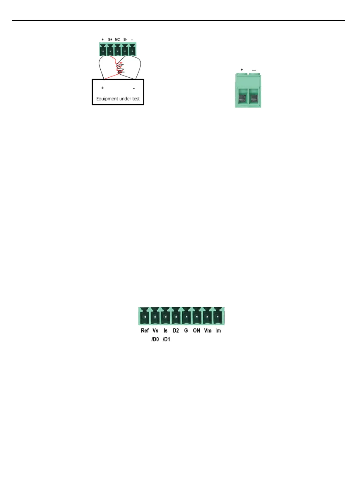
Terminal of external analog quantity: REF_10V Vs/D0 Is/D1 D2 ON/OFF Vm Im NULL GND which
correspond to the reference voltage, voltage control/digital quantity D0, current control/digital quantity D1,
digital quantity D2, turn on the output and close the control, voltage monitor and current monitor.
How to use the external analog control interface
 Loading...