User’s Manual UDP6900 Series Digital Control Power Supply
Instruments.uni-trend.com 35 / 44
You can use three channels of 0~10V analog signals to control the output on/off of the voltage, current and
power respectively; Vm and Im channels output 0~10V analog signals to monitor the voltage and current
output of the power supply respectively.
Terminal explanation as show in in the following table.
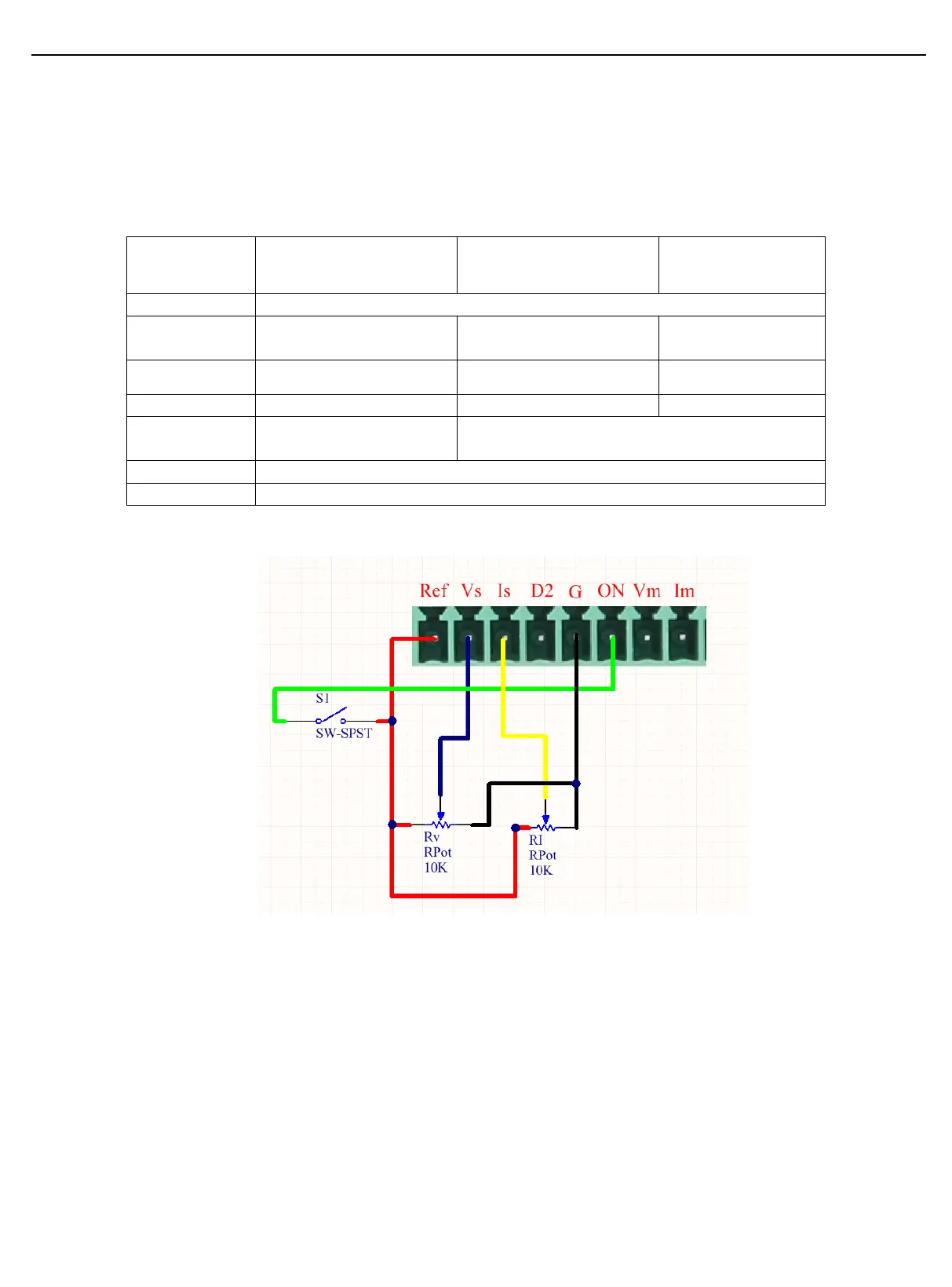
Connecting Example of External Analog Control Hardware
(1) As shown in the above figure, entering the output settings to set the operating mode to the
external analog control Ext-V.
(2) Slide to Rv or RI to set the value of voltage or current.
(3) Close S1 to turn on the output.
3.15.4 RS232 and RS485
RS232 DB9 and RS485 are using the same serial port.
External Analog Control Ext-V
External Digital Control
Ext-D
10V Regulated Voltage Output
Voltage analog control (0~10V)
Current analog control
(0~10V)
Power output the external control, high: turn on the
output; low: turn off the output
Voltage monitor analog quantity output (0~10V)
Current monitor analog quantity output 出(0~10V)
 Loading...