19
Testing for Continuity
To test for continuity, connect the Meter as below:
1. Insert the red test lead into VΩ
terminal and the black
test lead into the COM terminal.
2. Set the rotary switch to .
1. Connect the test leads across with the object being
measured.
4. The buzzer sounds continuously if the resistance of
a circuit under test is
10Ω, it indicates the circuit is
in good connection.
The buzzer does not sound if the resistance of a circuit
under test is>70Ω, it indicates broken circuit.
The buzzer may or may not sound if the resistance of
a circuit under test is between 10Ω to 70Ω.
The LCD displays the resistance value of a circuit
under test.
Note
The LCD displays “1” indicating the circuit being tested
is open.
When continuity testing has been completed,
disconnect the connection between the testing leads
and the circuit under test.
l
l
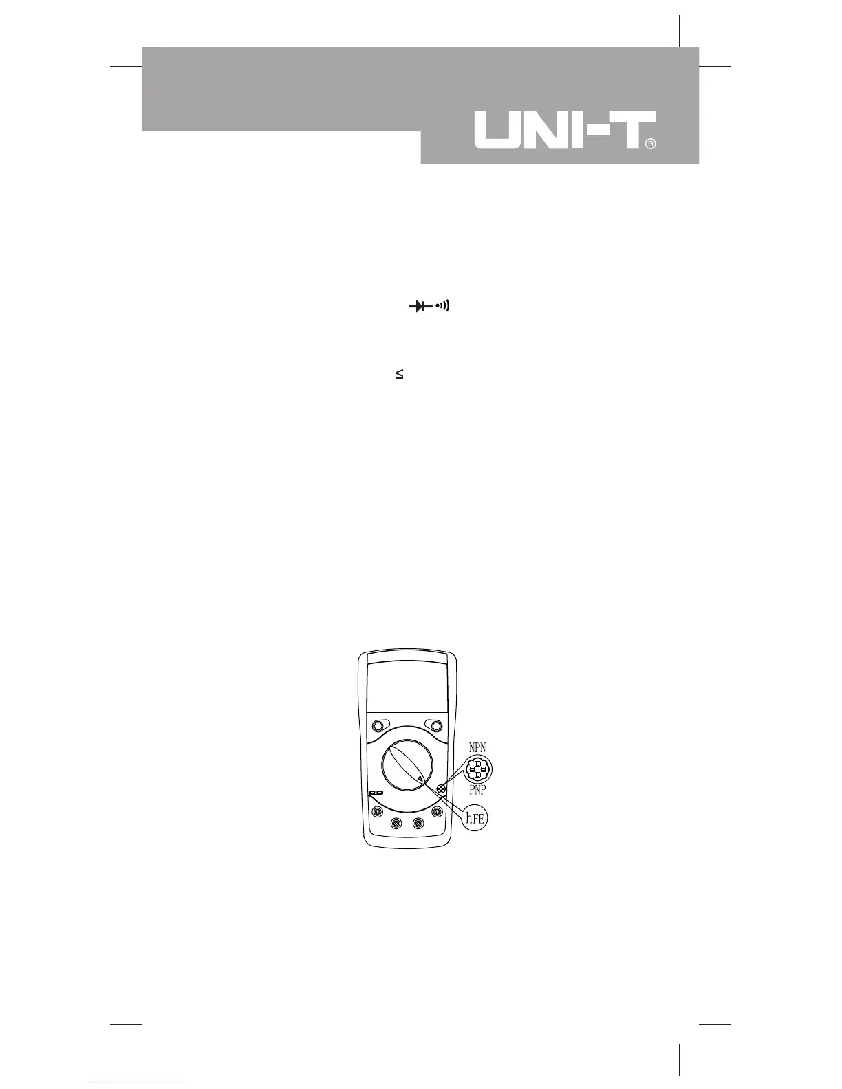
J. Measuring Transistor (see figure 9)
( figure 9)
To measure transistor, connect the Meter as follows:
1. Set the rotary switch to hFE.
2. Insert the NPN or PNP type transistor to be tested
into the transistor jack
3. The measured nearest transistor value shows on the
display
Model UT39A/B/C: OPERATING MANUAL

 Loading...