Deficiency of Built-In Battery
AC (Alternating Current)
AC or DC
Double Insulated
Warning. Refer to the Operating Manual
Conforms to Standards of European Union
Grounding
DC (Direct Current)
Diode
Continuity Test
Fuse
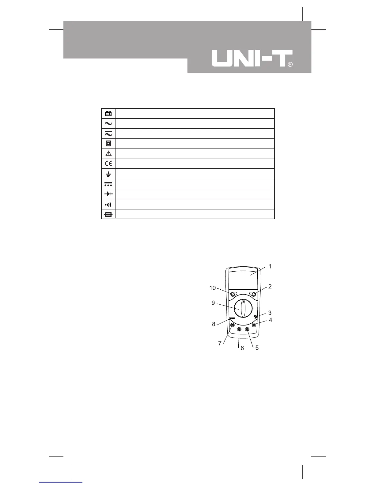
International Electrical Symbols
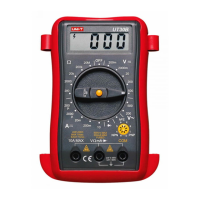
The Meter Structure (see figure 1)
1. LCD Display
2. Data Hold Button
3. Transistor Jack
4. COM Input Terminal
5. Other Input Terminals
6. mA Input Terminal
7. 20A/10A Input Terminal
8. Capacitance Jack
9. Rotary Switch
10. Power
( figure 1)
7
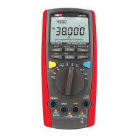
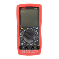
Model UT39A/B/C: OPERATING MANUAL

 Loading...