Operating Manual for UTD2000/3000
Probe compensatio
It needs to adjust it when connecting probe to an
input channel for the first time so that probe can be
appropriate to input channel. Probe without
compensation correction can also br ing i
measurement tolerance or error. Please operate
according to following steps for adjustment of
probe compensation
1. To set probe menu attenuation coefficient to
10× and place probe switch to 10× then connect
digital storage oscillograph probe to CH1. Please
guarantee reliable contact to probe. It has to
connect probe end to signal output connector
2
of
probe compensator then connect grounding clip to
earth wire connector of probe compensator. It als o
has to power on CH1 and press [AUTO]
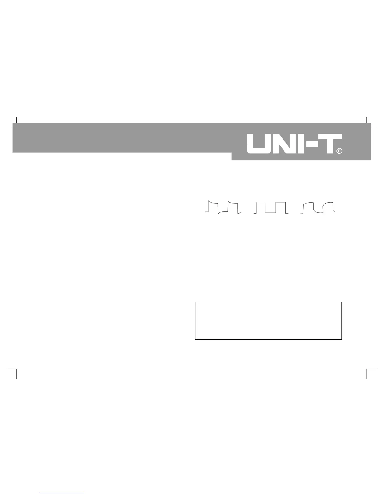
3. Adjust variable capacitance on the probe b
screwdriver of non-metallic handle for waveform
display of “insufficient compensation” or
“excessive compensation” shown in above figure
until “ correct compensation” for waveform displa
Warning: Please guarantee perfect insulatio
conduits of probe and do not contact metallic part
of probe when connecting to HV source to avoid
electric shock of probe during HV measurement
Observation of displayed waveform
8
Exceedin
Insufficient
compensation Figure 1
㧙
Compensation c orrection of probe

 Loading...

