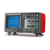
Oper ating Man ual fo r UTD 2000/3000
3
Setup of trigger system
Trigger can determine data acquisition time and
waveform display for digital storage oscillogr aph. It
can convert instable display to meaningful
waveform once correct setup. Digital storage
oscillograph will collect sufficient data to map
waveform in the left side of trigger point firstly. It
will acquire data continuously and synchronousl
when waiting for trigger conditions. It also will
acquire sufficient data continuously to map
waveform in the right side of trigger point. Trigger
control area of operation panel of digital storage
oscillograph includes trigger level adjus tm ent knob
and tr igger menu key of [TRIG MENU]
5.7-inch oscillograph will set 50% of trigger level i
vertical middle point of signal (and realize
UTD2000L /2000EX by press [SET TO ZERO] key)
It has to press forced trigger key of [FORCE]
Trigger level: Trigger level will set signal voltage
which corresponds to trigger point
50%: To set trigger level to vertical point of trigger
signal amplitude
FORCE: To produce 1 trigger signal forcefully for
mainly application for normal and single modes
shown in trigger modes
TRIG MENU: To trigger and set menu key

 Loading...


