+91 94273 01436
Sales: Email :
www.unitechinstrument.com
Website:
“Sure for service with hi-end versal nology”Uni Tech
Sales@unitechinstrument.com
Add.-503/504,Helix Complex , Opp. Surya Hotel, Sayajigunj, Vadodra-05. Gujrat. INDIA, PH-0265 6623551
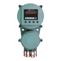
Model No. : UT-101 F
PAGE:3
INSTALLATION
zz
z
TERMINAL ARRANGEMENT
z
1. Phase
2. Neutral
3. RTD-Red wire, TC +
4. RTD-White wire, TC-
5. RTD-White wire, TC-, -mA, -V
6. +mA [4-20 / 0-20mA]
7. +V [0-10 / 0-5 / 1-5 / 3.5V]
8. +TPS [24VDC]
9. -TPS [24VDC]
10. D+ [RS-485]
11. D- [RS-485]
12. NC
13. C [RELAY]
14. NO
15. OUTPUT [OP+]
16. OUTPUT [OP-]
12345678910
11 12 13 14 15 16
SUPPLY
+mA
PN
+V
+TPS
-TPS
+
-mA/-V
NC1 C1 NO1
24VDC RELAY
CBA
T/C
--
RTD
T/C- T/C-T/C+
4~20mA 0~10VDC
D+ D-
RS-485
+OP -OP
OUTPUT
4-20mA
 Loading...