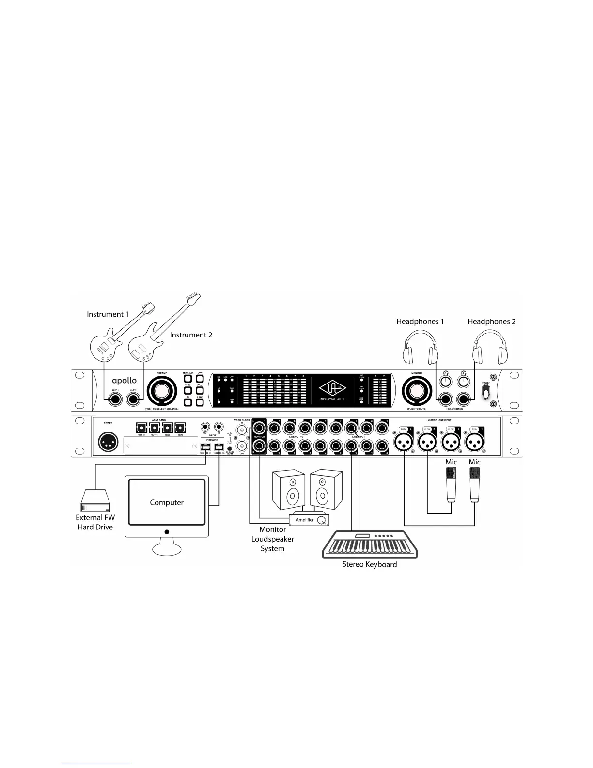
Typical Setup
This diagram illustrates an Apollo setup that might be used by two musicians that are recording
simultaneously. In this setup, only analog devices are connected; digital I/O is not used.
The example shows an electric guitar and electric bass connected to the Hi-Z inputs, and microphones are
connected to XLR inputs of channel 3 and 4. A stereo keyboard instrument is connected to line inputs 5 and 6,
and an external FireWire hard drive is “daisy-chained” to Apollo’s second FireWire port. Both headphone
outputs are used during tracking and the left/right monitor outputs are connected to a loudspeaker system for
mixdown.
Key points for this example:
• Mic/Line switch for channels 3 and 4 are set to “Mic”
• Unique mixes can be sent to each headphone output for “more me” during tracking
 Loading...