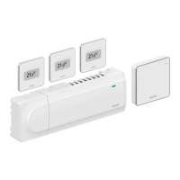
6. Attach communication module
Attach the communication module to the removable back mount.
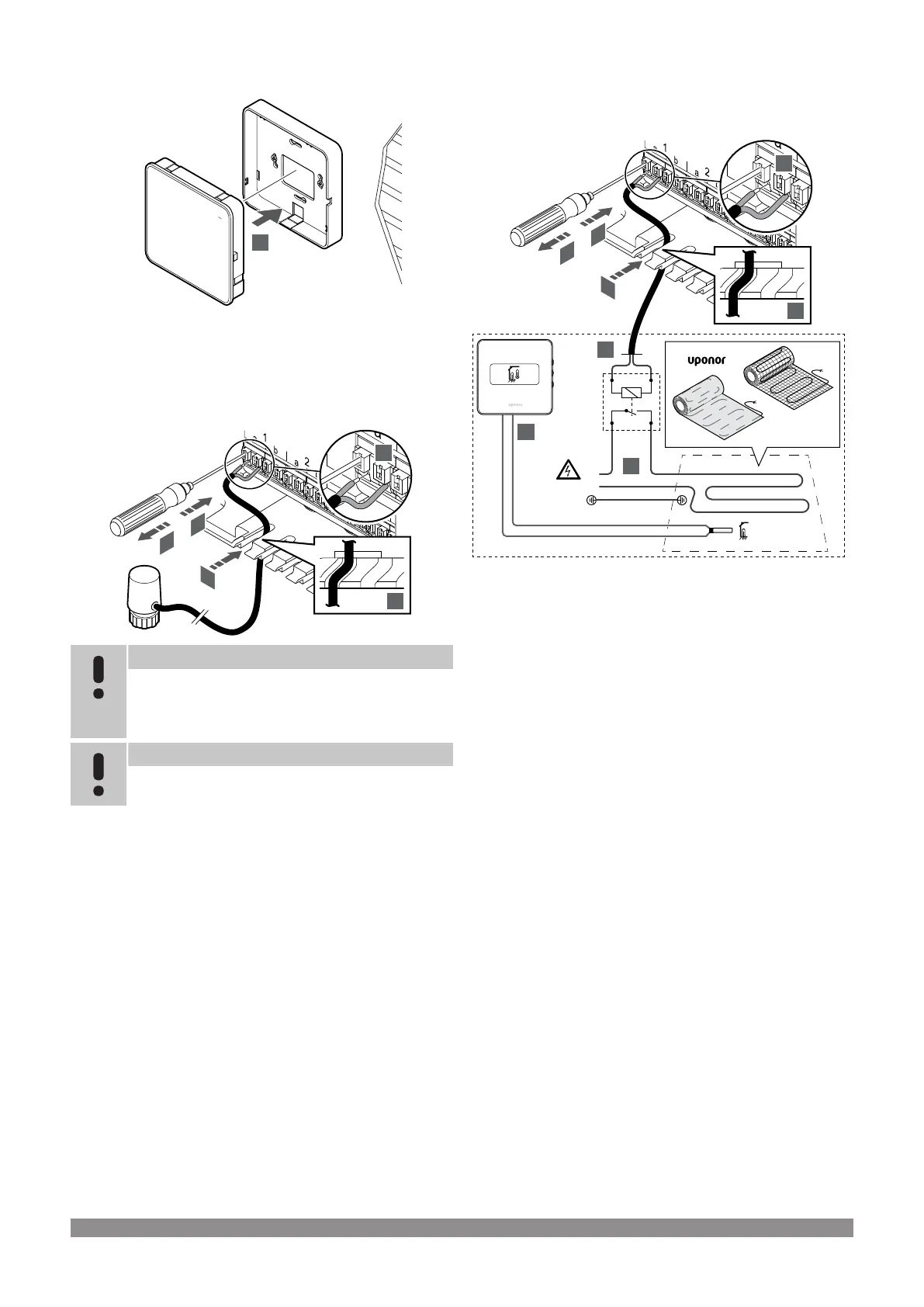
5.6 Connect actuators to room
controller
Note
Each thermostat can control one or more channels. To
simplify installation and maintenance, Uponor
recommends that actuators controlled by the same
thermostat shall be wired in sequence to the channels.
Note
Identify the room supplied by each loop on the manifold
and determine which channel it must be connected to.
1. Lead the cables from the actuators through cable entries in the
bottom of the room controller frame.
2. Press the white button on the quick connector, using a thin
screwdriver.
3. Insert a wire in the quick connector.
4. Remove the screwdriver.
5.7
Connect electrical underfloor
heating
230V~
50Hz
16(4)A
230V
24V AC
A2A1
L
N
5
3
1
2
7
3
4
6
SI0000162
1. Connect the electrical underfloor heating mat/wire to a 24V AC
relay dimensioned for the correct load.
• Connect load (L, 230 V), and the electrical underfloor
heating supply to a dry open contact.
2. Connect the 24V AC cables (to the room controller) to A1 and
A2 connection terminals on the relay.
3. Lead the cables from the relay through cable entries in the
bottom of the room controller frame.
4. Press the white button on the quick connector, using a thin
screwdriver.
5. Insert a wire in the quick connector.
6. Remove the screwdriver.
7. Install a floor sensor to a compatible room thermostat, and set
the control mode/DIP-switch.
• Digital thermostat: "Room temperature with external floor
sensor" (RFT)
• Public thermostat: "Room temperature sensor and floor
temperature sensor"
5.8 Connect thermostats to room
controller
The system is based on a bus communications protocol, utilising
daisy chain, direct or star topology connections. This makes wiring
and connection of thermostats and system devices much easier than
connecting one thermostat per connection terminal.
The wide array of connection possibilities presented with this
communications protocol can be combined in any way best suited for
the current system.
Uponor Smatrix Base PULSE
|
Installation and operation manual
|
25
 Loading...
