2
Dimensions/Weight
• 8.20" H x 4.55" W x 2.30" D
(20.83cm H x 11.56cm W x 5.84cm D)
• 1.5 lbs. (.68 kg)
Power Requirements
-21.5 to -26VDC "B" Battery, 200mA maximum
Environment
Temperature: 0 to +50 Degrees C
Humidity: 0 to 85% non-precipitating
DESIGN
General
The Valcom V-9936A is designed to monitor up to six
C. O. lines or PABX station numbers and will provide
a common tone signal and contact closure whenever
any of the lines are ringing. The V-9936A may be
used with most telephone systems because it
connects directly to the lines and not to the phones.
The tone output may be connected to speakers used
only for ringing or to one zone of a paging system.
The dry contact closure may be used to activate loud
ringing bells, strobes or other external equipment.
Both outputs will provide interrupted signals
whenever any line is ringing.
A disable input is provided for connection of a night
switch. With no switch connected, the V-9936A will
signal any time a line rings in. With a switch
connected and providing a short across the disable
input, the unit will be inactive.
Stand-Alone Ringing
The following components are required to provide
common audible ringing over dedicated bells or
speakers.
• V-9936A C. O. Ring Units, 1 per 6 lines
• Signaling Devices consisting of:
a. Two 45 Ohm talkback speakers or
b. Up to 150 one-way amplified speakers or
c. Loud bells, buzzers, strobes etc. as required
• Power Supply: The VP-624B will power a V-9936A
using talkback speakers for signaling. If one-way
speaker assemblies or other signaling devices are
used, additional power may be required.
Ringing Over Paging
Ringing may be connected to one zone of a Valcom
One-way or Talkback Paging System or to the INPUT
of a high powered amplifier. The following
components are required:
• V-9936A C. O. Ring Units, 1 per 6 lines
• VP-624B -24VDC Power Supply (VP-4024C if
using more than (3) V-9936A's).
If a page is in progress when an incoming call is
detected, the ring signal from the V-9936A will
momentarily override the page.
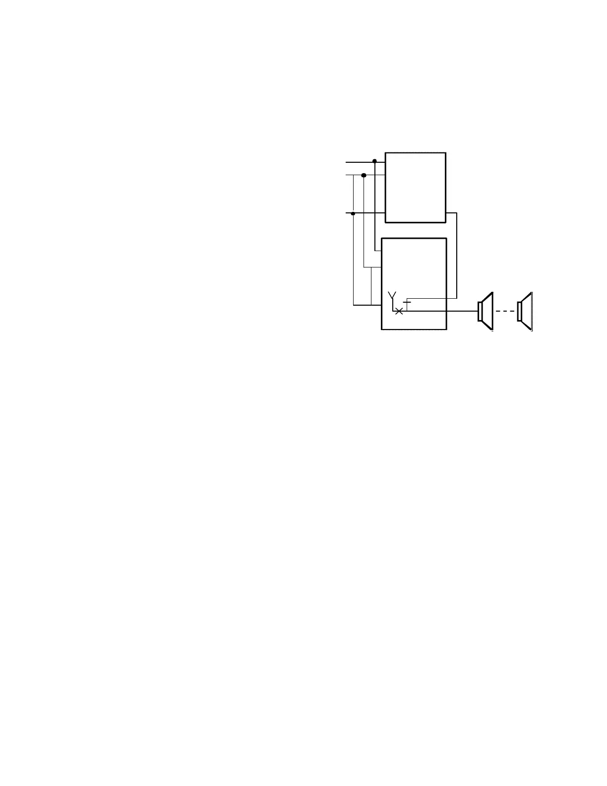
FIGURE 1 - TYPICAL INSTALLATION
INSTALLATION
The following sections contain step-by-step
instructions for wiring the V-9936A and associated
Valcom equipment. Each instruction is preceded by a
line; place a check on the appropriate line as the
instruction is completed. The instructions also
include tests along the way to verify connections
have been made correctly. If these steps are followed
exactly, installation should go smoothly and quickly.
If the results of a test do not correspond with what is
shown, DO NOT PROCEED UNTIL THE PROBLEM
HAS BEEN CORRECTED.
Set individual volume controls at approximately 1/2
volume for testing when installing the control unit
and any one-way amplified speaker assemblies.
Mounting
Remove the metal mounting plate from the rear of the
V-9936A enclosure. Using two #6 x 3/4" wood
screws, mount the plate in a vacant space on the
backboard with the telephone system common
equipment. Both mounting holes must be utilized to
insure secure mounting of the unit. See Figure A.
Open the V-9936A enclosure to access connections
and option switches. Slide the rear of the unit
(Contains the board) onto the mounting plate and
lock in place with screw provided. Make connections
and replace cover after all connections are
accomplished. Lock cover in place using the #6 x 1/2"
screw provided.
C.O.1
C.O.2
C.O.6
TELEPHONE
SYSTEM
PAGE
OUT
V-9936A
WARBLE
TONE
GENERATOR
(Page Control Unit
may not be required)
 Loading...