4
DO NOT locate the V-9936A or its wiring closer
than 18" to a power supply or any equipment
that generates electrical noise.
Power Connections
NOTE: The steps below must be completed for each
V-9936A being installed.
__ 1. Unplug power supply.
__ 2. Connect -24VDC "B" battery (May be
referred to as "-" or "signal battery") from
power supply to pin 30 (-24VDC) on the
V-9936A.
__ 3. Connect -24VDC Ground ("B" ground, "+"
or "signal" ground) from power supply to
pin 29 (GND).
__ 4. Connect -24VDC ground (+) from power
supply to telephone system GND.
__ 5. Power Test:
__ a. Plug in power supply.
__ b. If power reversal LED is lit -
(If not lit, go to step 6).
__ (a) Unplug power supply.
__ (b) Reverse connections on V-9936A, pins
29 (GND) and 30 (-24VDC).
__ (c) Go to step 6.
__ 6. Unplug power supply.
15
30
1
16
HiZ
LoZ
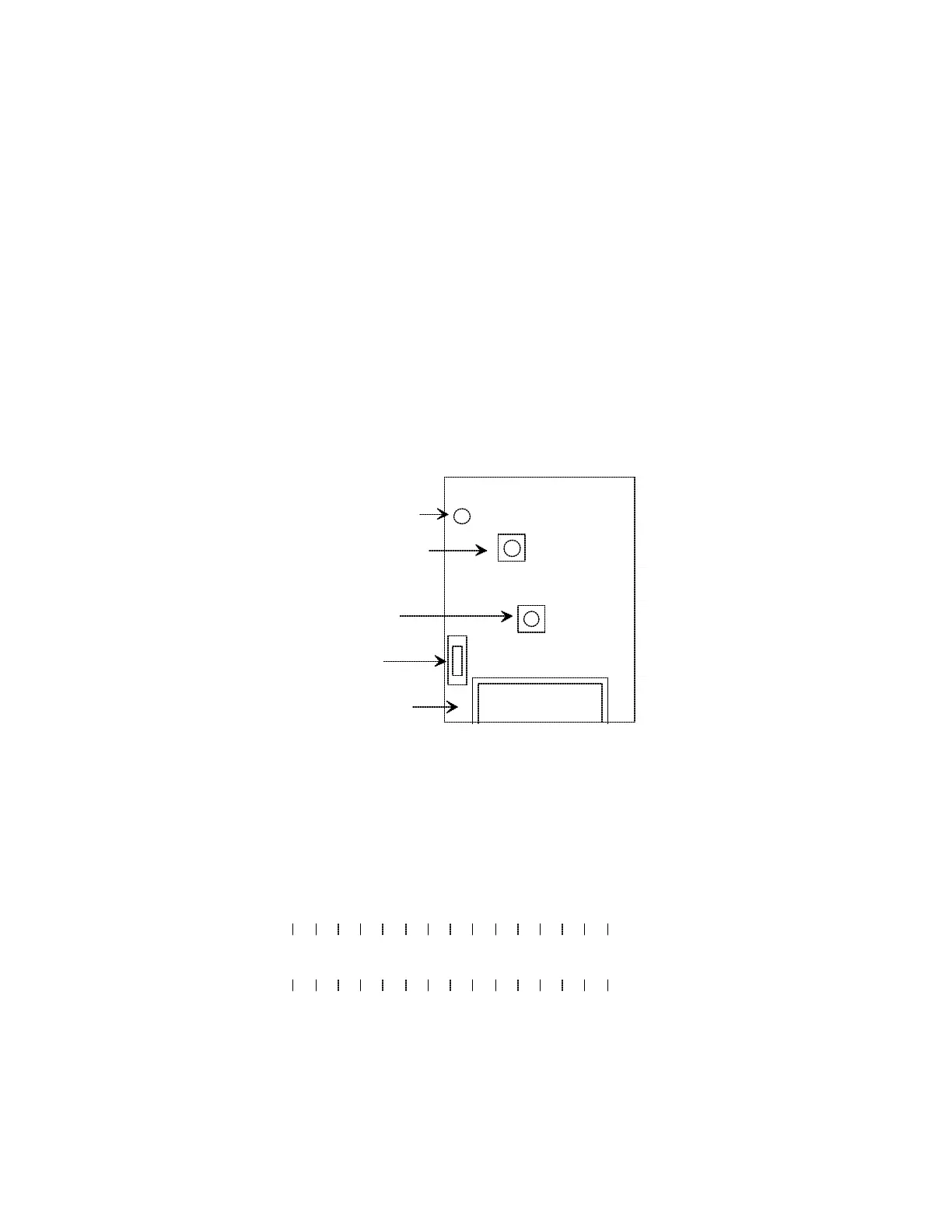
V-9936A
Do Not Adjust
Speaker Select
Switch
Volume Control
Reverse Power LED
Connecting Block
LOCATION OF CONNECTING BLOCK AND CONTROLS
15 14 13 12 11 10 9
8 7 6 5 4 3 2 1
30 29 28 27 26 25 24 23 22 21 20 19 18 17 16
-24VDC OUT
GROUND OUT
PAGE IN T
CONTACT CLOSURE
PAGE OUT T
-24VDC OUT
DISABLE IN
EXPANSION
C.O.6 TIP
C.O.5 TIP
C.O.4 TIP
C.O.3 TIP
C.O.2 TIP
-24VDC IN
GROUND IN
PAGE IN R
CONTACT CLOSURE
PAGE OUT R
GROUND OUT
DISABLE OUT
C.O.6 RING
C.O.5 RING
C.O.4 RING
C.O.3 RING
C.O.2 RING
CONNECTING BLOCK PIN DESIGNATIONS
FIGURE 2
 Loading...