X2-OPERATIONS MANUAL BUTTON DISPLAY
Doc: 70-00-0950A, Serie X2, 20211220 © Vector Controls GmbH, Schweiz Page 4-16
Subjects to alteration www.vectorcontrols.com
Cooling mode activates cooling equipment for temperatures above the set point.
Heating mode activates heater for temperatures below set point.
Set clock, change time schedules or indication of set time schedules
The side bars show the fan speed.
Alarm / Error active (see chapter 2.6 and 2.7)
Status LED is on or blinks briefly once every 5 seconds
Status LED blinks every second in case there is an alarm or error condition
2.6 Alarm messages
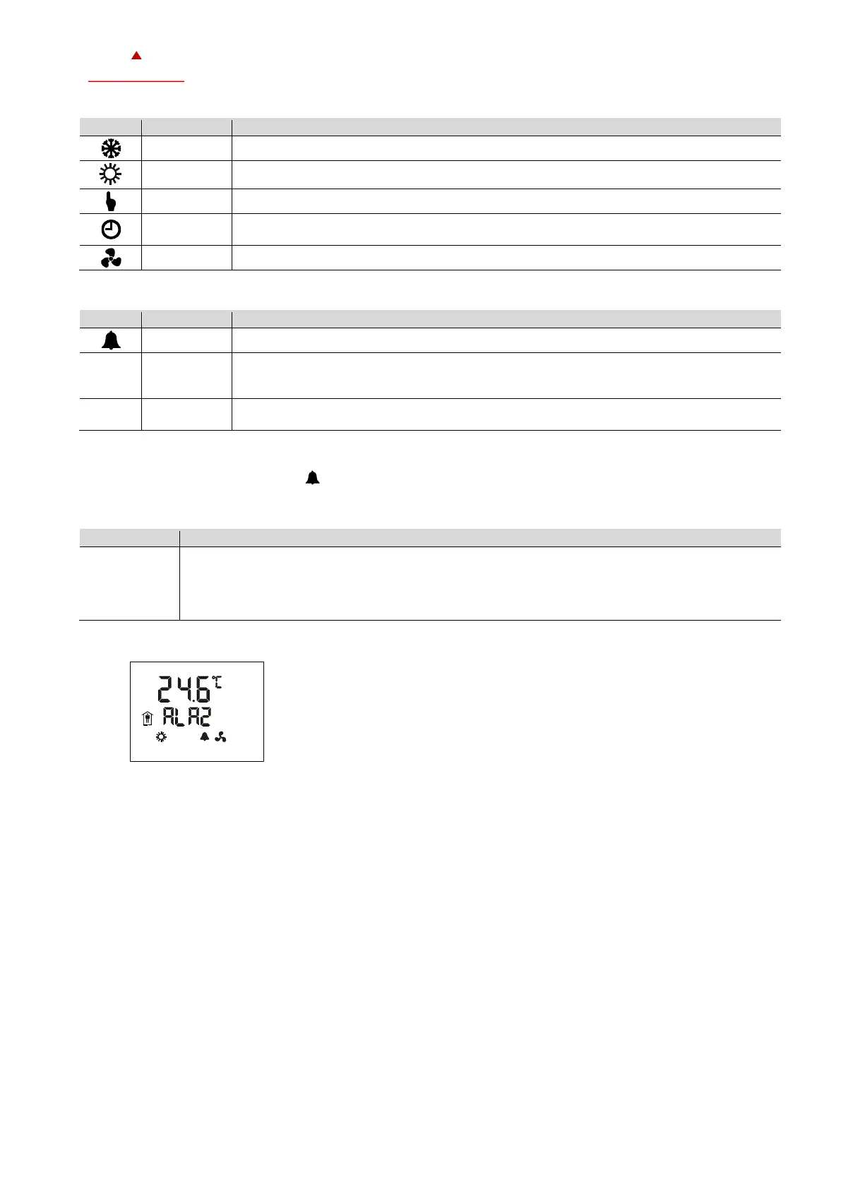
If an alarm is active, the alarm symbol is set and an alarm message is shown on the small digits.
Some alarms can be confirmed by pressing the "Right" button.
Up to 8 different alarms can be displayed.
The alarm condition is programmable and must be defined when configuring the controller.
See separate alarm list for the meaning of the programmed alarms. The list is provided by the
configurator of the X2 device.