2
INSTALLATION
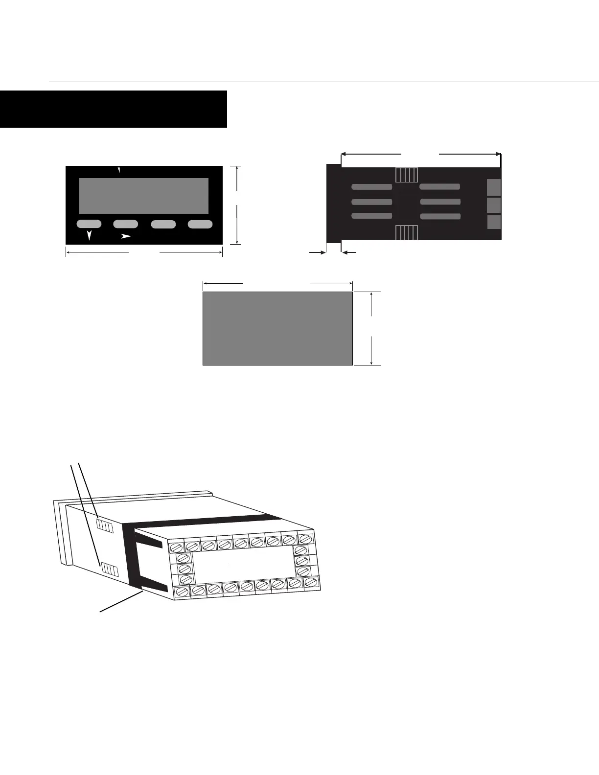
PANEL MOUNTING
100mm
10mm
Mounting Grooves
The instrument can be mounted in a panel with a thickness of up to 6mm. The
cutout(s) should be made based on the recommended panel opening illustrated in the
drawing above.
Insert the unit in the panel through the cutout. Ensure that the
panel gasket is not distorted and the instrument is positioned
squarely against the panel. Slide the mounting clamp into place
on the instrument, as shown to the left, and push it forward until
it is firmly in contact with the rear face of the mounting panel and
the tabs on the bracket arm are seated in the mounting grooves
on the side of the unit.
The electronic components of the instrument can be removed from
the housing after installation without disconnecting the wiring.
To remove the components, grip the side edges of the panel and
pull the instrument forward. Take note of orientation of the unit
for subsequent replacement in the housing.
Bracket Arm
2
345678
24
23
22
14 15 16 17 18 19 20
10 11 12
VEEDER-ROOT
PGM
RST
OP1
OP2
48mm
96mm
82344
PANEL
CUTOUT
SIZE
45mm
+0.5 -0.0
92mm +0.5 -0.0
www.TheTimerAndCounterCompany.com

 Loading...