3
INSTALLATION
WIRING
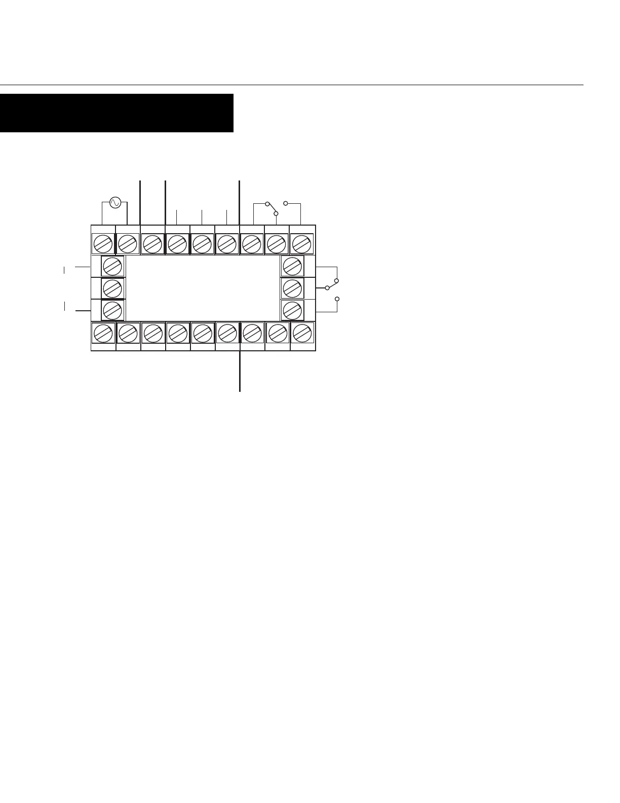
REAR TERMINAL CONNECTIONS
Terminals 11 & 15 are not used.
Count Inputs
Terminal #2 is the connection for Input A, which is programmable to be
the rate channel and total. Terminal #1 is the connection for Input B,
which is programmable to be an incrementing input, a decrementing
input, or channel B of encoder input. Input B cannot be used for rate - it
only serves as a secondary input for total. The common connection for
both Input A and Input B is Terminal #3.
Control/Digital Inputs
A contact closure or NPN signal can be used to activate preconfigured
functionality. Terminal # 5 is used for a remote reset function, while
Terminal #6 is a security function, that when active, will prohibit entry
into Program Mode. Terminal #8 serves as the common for both of these
inputs.
Auxiliary Power Output
A 9 - 15 VDC for powering external sensors and encoders up to 125 mA
can be accessed by connecting the positive supply side of the sensor to
Terminal #4 and the negative side to Terminal #8.
Linear Output
An option board may be installed that provides a 10 bit linear output
signal relative to the Rate Value. Terminal #12 is the positive side of the
connection, and Terminal #10 is the negative side. The default range of
the output is 4-20 mA, but can be changed via the front panel to 0-20
mA, 0-10 VDC, 2-10 VDC, 0-5 VDC, or 1-5 VDC.
Input Power
For an AC powered unit, Terminal #13 serves as the line
or Hot side connection for AC powered units and as the
positive side for DC powered units. The neutral side for
AC powered units and the negative side for DC powered
units are connected to Terminal #14.
Transistor Outputs
Your unit comes standard with 2 NPN outputs which are activated by
each of the alarms. Transistor Output 1, which is tied to the High Alarm
Value, is on Terminal #7. Transistor Output 2, which is tied to the Low
Alarm Value, is on Terminal #9. Terminal #8 serves as the common
connection for both transistor outputs.
Relay Outputs
Your unit comes standard with a relay output which is tied to the High
Alarm Value. Terminal #19 is NC, Terminal #20 is common, and
Terminal #21 is NO. A second relay output tied to the Low Alarm Value
can be added as an option at the time of order or later installed in the
field. Terminal #22 is NC, Terminal #23 is common, and Terminal #24 is
NO.
Serial Communication
An RS-485 communication board, utilizing ASCII protocol, can be
installed as an option. Terminals #16 & #17 serve as the B and A
connections respectively, while Terminal #18 is connected as the
common.
23 4 5 6 78
24
23
22
14 15 16 17 18 19 20
10 11 12
B A
COM
Power Supply
+ VDC -
RS-485 Comm.
(opt.)
Input B
Input A
Input Common
Aux. Power
(opt.)
Digital In 1
(rem. reset)
Digital In 2
(sec. lockout)
Common
+
-
Linear
Output
(opt.)
Relay 2
(opt.)
Relay 1
NPN Out 1
(HI)
NPN Out 2
(LO)
www.TheTimerAndCounterCompany.com

 Loading...