Installation Guide Mag Sump Sensor Installations - Dispenser Pan Sump
20
Mag Sump Sensor Installations - Dispenser Pan Sump
1. A transmitter /battery pack pair can be installed with a Veeder-Root Mag Sump sensor within the
dispenser sump.
2. Install the Mag Sump sensor in the dispenser’s pan area following instructions accompanying the sensor.
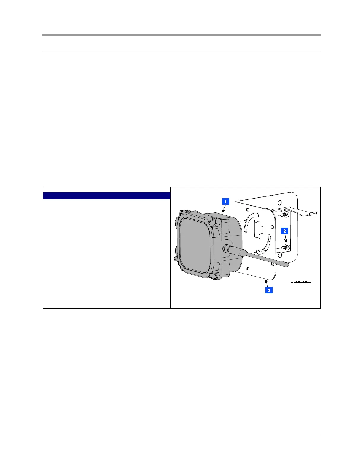
3. Using two taptite screws from the kit, attach the transmitter housing to the side of the battery support
bracket that has the two circular slots (see Figure 19). Do not tighten screws at this time.
4. Get the 1 inch by 6 inch slotted flat bar from the kit and two ¼ x 3-inch bolts and two nuts. Clamp the
bracket to a section of the square support tubing in the sump, below the shear valve (see Figure 20).
5. Rotate the transmitter antenna as close as possible to a horizontal position then tighten two mounting
screws in housing.
6. Insert the battery pack into its support bracket - do not connect battery cable to battery pack at this time.
7. Attach power/sensor cables as described in the section below entitled Connecting cables to the
Transmitter.
LEGEND FOR NUMBERED BOXES IN FIGURE 19
1. Transmitter
2. #10 x 1/2” taptite screws (2)
3. Battery support bracket
Figure 19. Attaching transmitter to battery support bracket
 Loading...