Installation Guide Safety Precautions
4
Site Considerations - Control Drawing
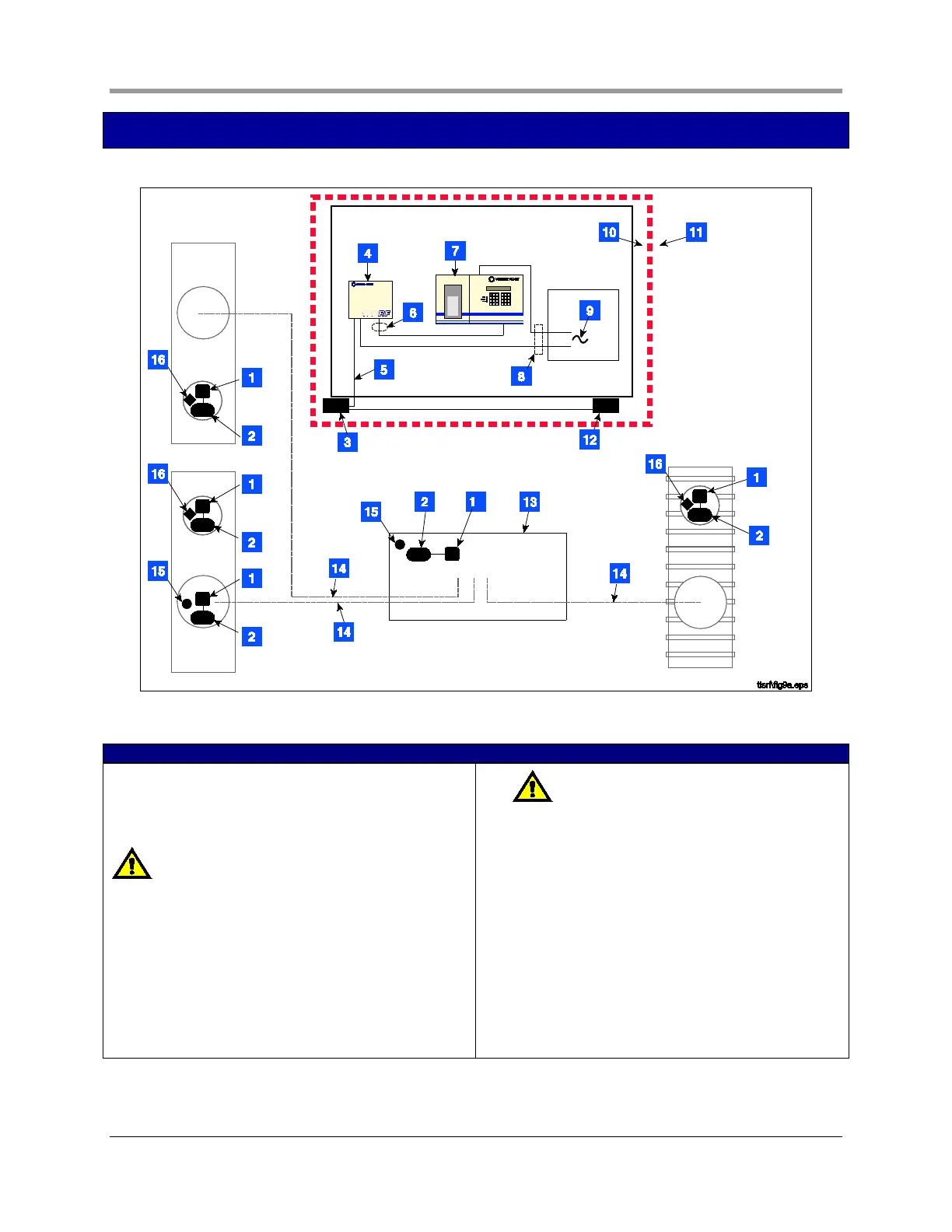
Figure 1. Control Drawing - Example TLS RF Wireless System Site Layout
LEGEND FOR NUMBERED BOXES IN FIGURE 1
To be installed in accordance with the National Electrical
Code, NFPA 70 and the Code for Motor Fuel Dispensing
Facilities and Repair Garages (NFPA 30A), or other local
code such as the CEC, Canadian Electrical Code.
WARNING! Substitution of components may impair
intrinsic safety.
Circuitry within the console barrier forms an intrinsically
safe, energy-limited system. This system is intrinsically safe
for use in a Class I, Group D hazardous location.
1. Battery Pack
2. Transmitter
3. Receiver
4. TLS RF (Vm = 250 V)
5. RS-485 Cable (Belden #3107A or equiv.)
6.
NOTE: Intrinsically safe wiring shall be installed
in accordance with Article 504-20 of the NEC, ANSI/
NFPA 70. Maximum probe/sensor cable length 1000
ft. (304 m).
7. TLS console (Vm = 250 V)
8. Conduit that enters power wiring knockout.
9. 120 or 230 Vac from power panel.
10. Non-hazardous area
11. Hazardous area (Class I, Div. 1, Group D)
12. Repeater (1)
13. Dispenser sump
14. Underground product line
15. Sump sensor
16. Mag probe
 Loading...