19
4 Mounting
VEGAPULS 68 • Foundation Fieldbus
36538-EN-170405
4.4 Mounting instructions
The illustrations with the following mounting instructions show a radar
sensor with horn antenna. The mounting instructions apply analo-
gously also to the version with parabolic antenna.
The emitted radar impulses of the radar sensor are electromagnetic
waves. The polarisation is the direction of the electrical wave compo-
nent.Byturningtheinstrumentintheconnectionangeormounting
boss,thepolarisationcanbeusedtoreducetheeectsoffalse
echoes.
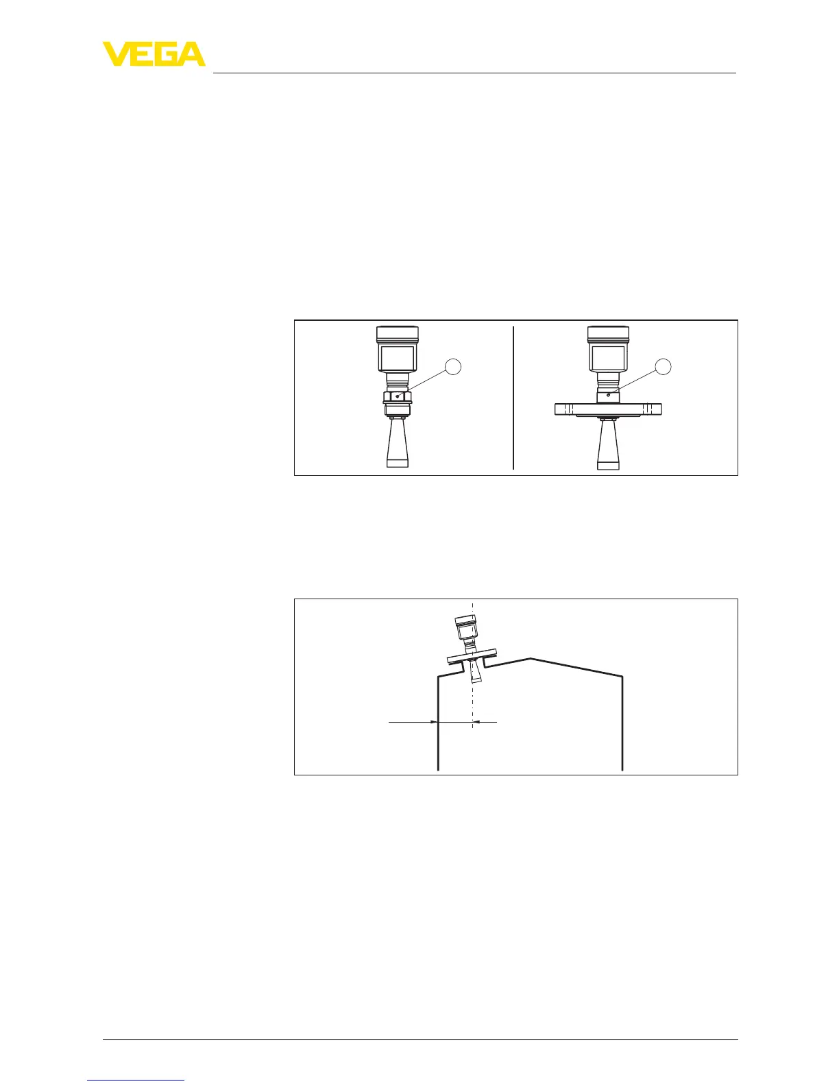
Thepositionofthepolarisationismarkedontheprocessttingofthe
instrument.
1
2
Fig. 5: Position of the polarisation
1 Marking with screwed version
2 Markingwithangeversion
Mount the sensor at least 200 mm (7.874 in) away from the vessel
wall.
200 mm
(7.87
")
Fig. 6: Mounting the radar sensor on the vessel top
If you cannot maintain this distance, you should carry out a false
signal suppression during setup. This applies particularly if buildup on
the vessel wall is expected. In such cases, we recommend repeating
the false signal suppression at a later date with existing buildup.
Mountingshouldnotbetooclosetotheinowingmaterialasthe
microwave signal will be interferred. The optimum mounting position is
ontheoppositeofthelling.Toavoidstrongpollution,thedistanceto
thelterordustextractionmustbeasbigaspossible.
Horn and parabolic
antenna
Polarisation
Installation position
Inowingmedium
 Loading...