38
5 Connecting to the bus system
VEGAPULS 68 • Foundation Fieldbus
36538-EN-170405
Contact pin Colour, connection ca-
ble in the sensor
Terminal, electronics
module
Pin 2 White 6
Pin 3 Blue 7
Pin 4 Black 8
5.6 Double chamber housing with
VEGADIS-Adapter
3
1
2
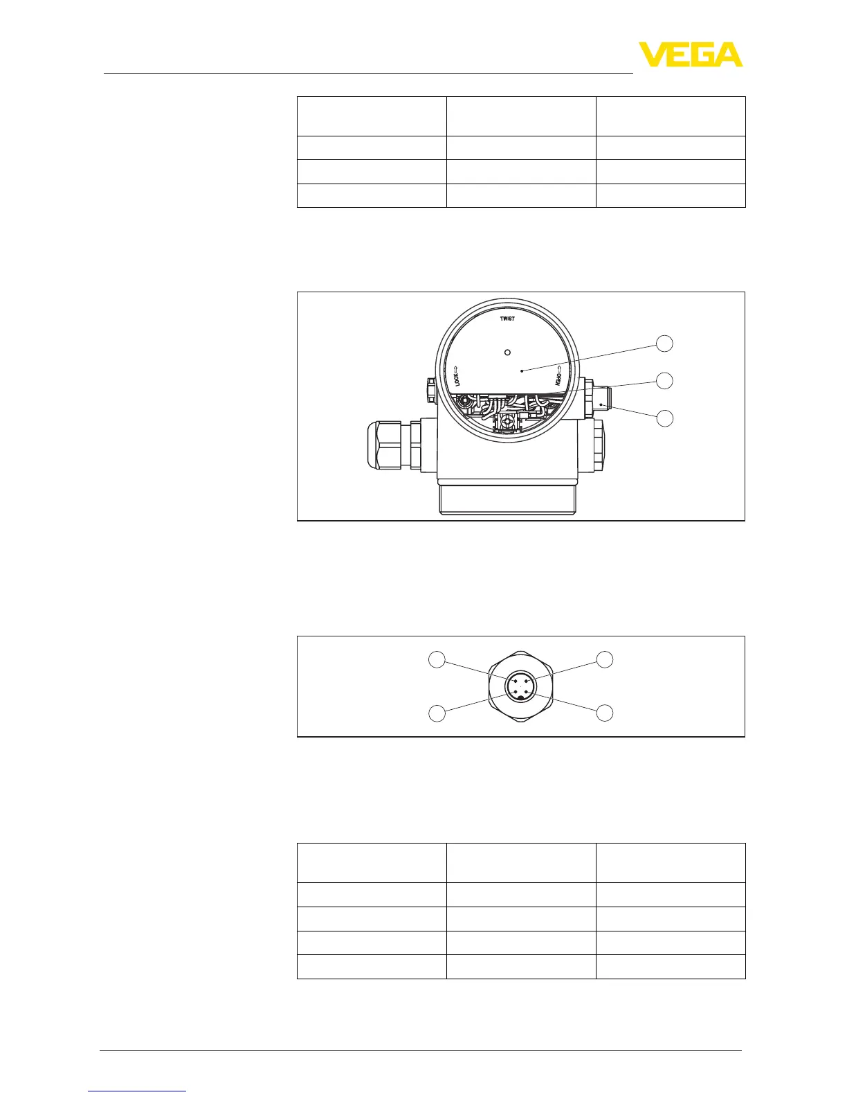
Fig. 35: View to the electronics compartment with VEGADIS adapter for connec-
tion of the external display and adjustment unit
1 VEGADIS adapter
2 Internal plug connection
3 Plug connector M12 x 1
34
1
2
Fig. 36: View to the plug connector M12 x 1
1 Pin 1
2 Pin 2
3 Pin 3
4 Pin 4
Contact pin Colour, connection ca-
ble in the sensor
Terminal, electronics
module
Pin 1 Brown 5
Pin 2 White 6
Pin 3 Blue 7
Pin 4 Black 8
Electronics compartment
Assignment of the plug
connector
 Loading...