35
5 Connecting to the bus system
VEGAPULS 68 • Foundation Fieldbus
36538-EN-170405
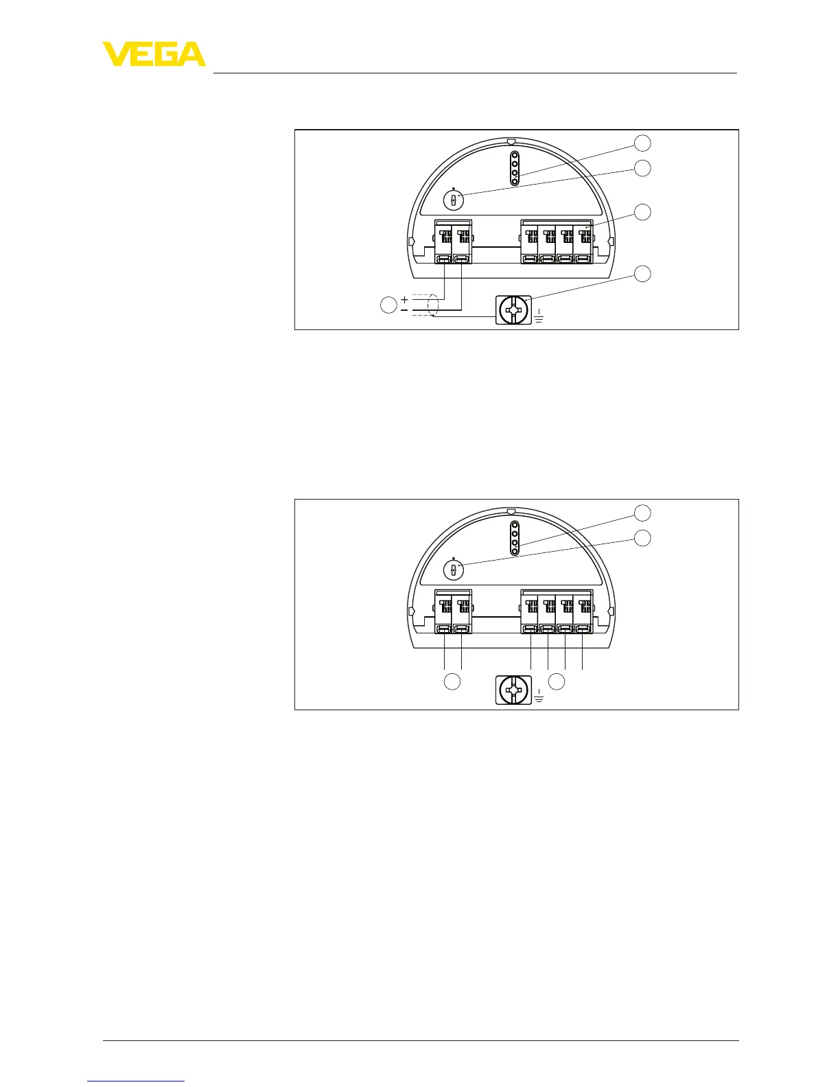
5.3 Wiring plan, single chamber housing
1
2
( )
(-)
1
5
0
1
0
1
+
678
Bus
3
4
5
Fig. 28: Electronics and terminal compartment - single chamber housing
1 Voltage supply, signal output
2 Contact pins for the display and adjustment module or interface adapter
3 Simulation switch ("1" = mode for simulation release)
4 For external display and adjustment unit
5 Ground terminal for connection of the cable screen
5.4 Wiring plan, double chamber housing
5
0
1
0
1
+
678
Bus
3
1
2
( )
(-)
11
Fig. 29: Electronics compartment - double chamber housing
1 Internal connection to the terminal compartment
2 Contact pins for the display and adjustment module or interface adapter
3 Simulation switch ("1" = mode for simulation release)
Electronics and terminal
compartment
Electronics compartment
 Loading...