1 NOMENCLATURE AND COMPONENTS
This section describes the number for Liebert® CW units and components.
1.1 Liebert CW Model-number Nomenclature
The following tables describe each digit of the configuration number. The 14-digit model number consists
of the first 10 digits and last 4 digits of the configuration number.
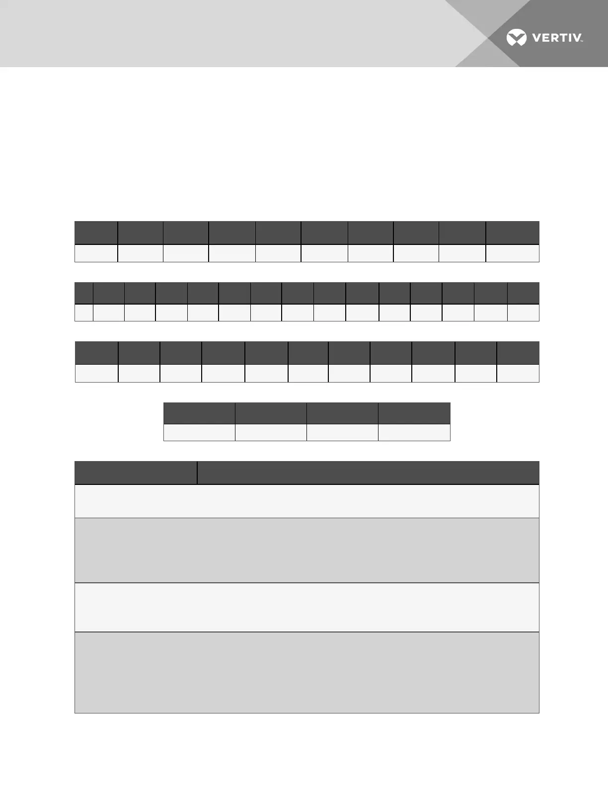
1 2 3 4 5 6 7 8 9 10
C W 4 1 5 D 1 3 A 1
Table 1.1 CW Model Number Example Digits 1 to 10
11 12 13 14 15 16 17 18 19 20 21 22 23 24 25
1 2 0 8 1 0 L 0 0 0 P 0 0 0 0
Table 1.2 CW Configuration-number Detail Digits 11 to 25 Example
26 27 28 29 30 31 32 33 34 35 36
0 0 0 0
0 0 0 0 0 0 0
Table 1.3 CW onfiguration-number Detail Digits 26 to 36
37 38 39 40
# # # A
Table 1.4 CW Model Number Digits37to40Example
Digit Description
Digits 1 and 2 = Unit Family
CW = Liebert® CWfloor-mounted, chilled-water unit
Digit 3, 4, 5 = Nominal Cooling Capacity, kW
305 = 305kW
375 = 375kW
415 = 415kW
Digit 6 = Air Distribution
H = Horizontal discharge
D =Bottom discharge
Digit 7 = Electric Panel Options
1 =Data hall or Bottom discharge, left electric panel
2 = Data hall or Bottom discharge, right electric panel
3 = Gallery, left electric panel
4 = Gallery, right electric panel
Table 1.5 CW Model-number Digit Definitions
1 Nomenclature and Components
7

 Loading...


