2 PRE-INSTALLATION PREPARATIONANDGUIDELINES
NOTE: Before installing unit, determine whether any building alterations are required to run piping,
wiring and duct work. Follow all unit dimensional drawings and refer to the submittal engineering
dimensional drawings of individual units for proper clearances.
Refer to Table 1.5 on page7, and submittal drawings to determine the type of system being installed and
anticipate building alterations, piping and duct work needed.
The unit dimensions, pipe-connection locations, and piping schematics are described in the submittal
documents included in the Submittal Drawings on page45.
• Verify that the floor is level, solid and sufficient to support the unit. See Table 2.2 on the next
page,for unit weights.
• Confirm that the room is properly insulated and has a sealed vapor barrier.
• For proper humidity control, keep outside or fresh air to an absolute minimum (less than 5% of
total air circulated in the room).
• Do not install a Liebert® CW in an alcove or at the end of a long, narrow room.
• Install the units as close as possible to the largest heat load.
• Allow at least the minimum recommended clearances for maintenance and service. See the
appropriate submittal drawings for dimensions.
• We recommend installing an under-floor water detection system. Contact your Vertiv
representative for information.
2.1 Planning Dimensions
The unit, floor stand, and plenum dimensions are described in the submittal documents included in the
Submittal Drawings on page45.
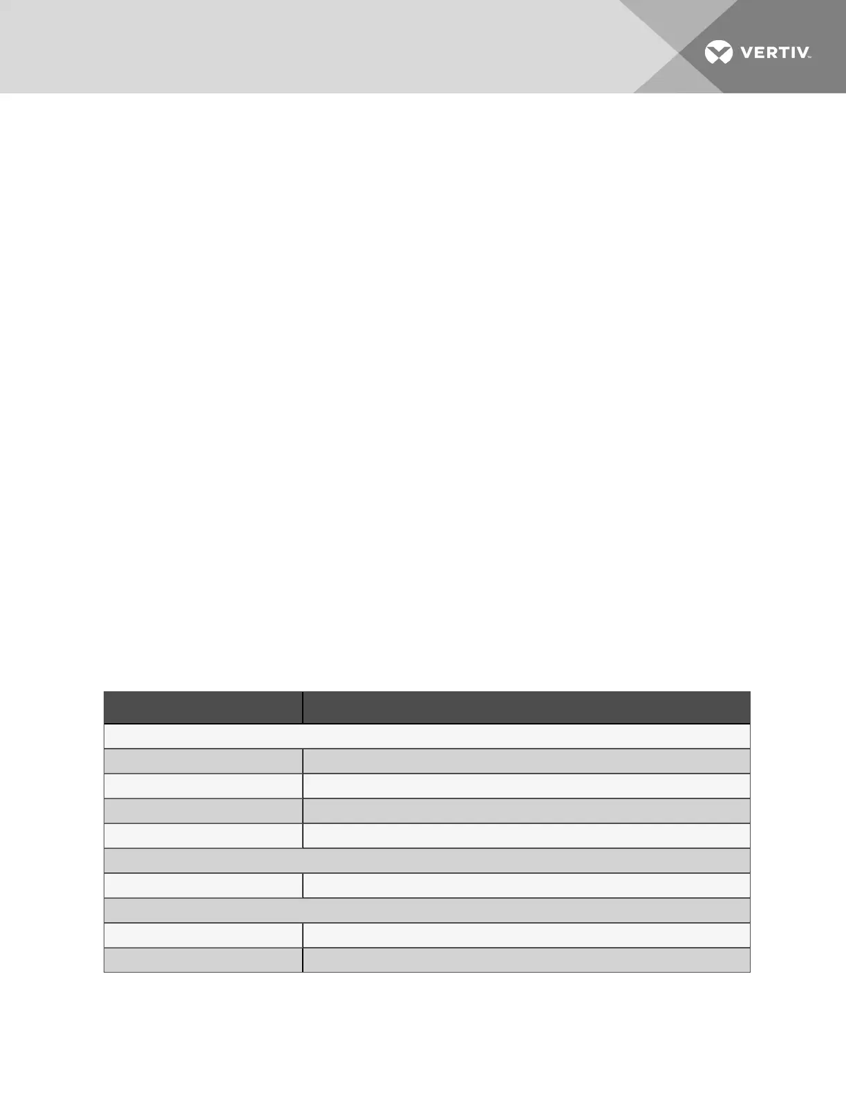
The following table lists the relevant documents by number and title.
Document Number Title
Downflow Units
DPN004862 Cabinet and Plenum Dimensional Data, Downflow, Horizontal Discharge
DPN004900 Cabinet and Plenum Dimensional Data, Downflow, Bottom Discharge
DPN004870 Installation and Service Clearance Data, Downflow, Horizontal and Bottom Discharge
DPN004869 Floor planning dimensional data for adjacent units
Floor Stands
DPN004866 Floorstand Dimensional Data,
Airflow Schematic
DPN004865 Airflow Schematic, Downflow, Horizontal Discharge
DPN004904 Airflow Schematic, Downflow, Bottom Discharge
Table 2.1 Dimension Planning Drawings
2 Pre-installation PreparationandGuidelines
11

 Loading...


