5 PIPING REQUIREMENTS
All fluid connections to the unit, with the exception of the condensate drain, are sweat copper. Factory-
installed piping brackets must not be removed. Field-installed piping must be installed in accordance with
local codes and must be properly assembled, supported, isolated and insulated. Avoid piping runs
through noise-sensitive areas, such as office walls and conference rooms.
Refer to specific text and detailed diagrams in this manual for other unit-specific piping requirements.
All piping below the elevated floor must be located so that it offers the least resistance to air flow. Careful
planning of the piping layout under the raised floor is required to prevent the air flow from being blocked.
When installing piping on the subfloor, we recommend that the pipes be mounted in a horizontal plane
rather than stacked one above the other. Whenever possible, the pipes should be run parallel to the air
flow.
The pipe connection locations, piping general arrangement and schematics are described in the
submittal documents included in the Submittal Drawings on page45.
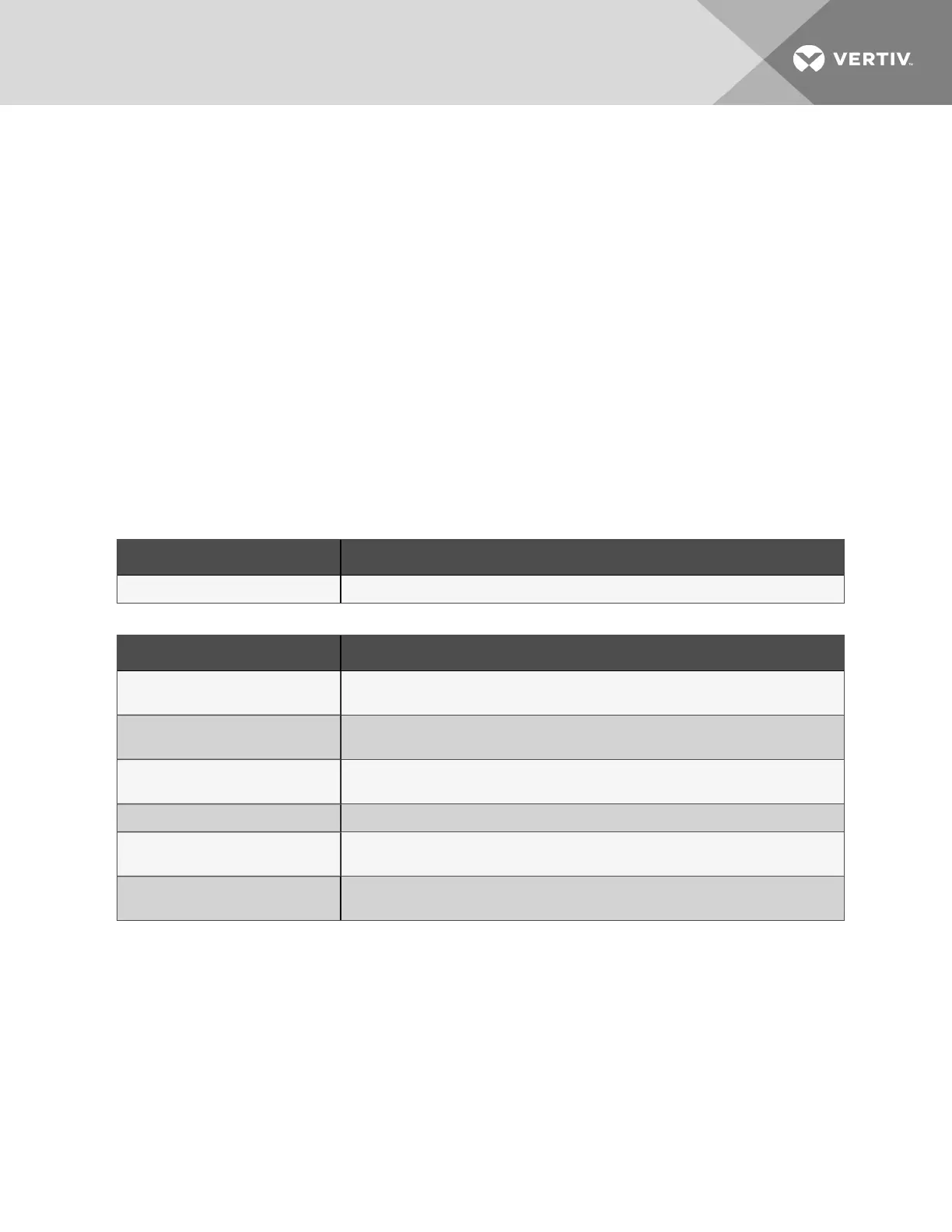
The following tables list the relevant documents by number and title.
Document Number Title
DPN004952 Piping Schematic, Downflow, CW305, 375, 415
Table 5.1 Piping General-arrangment Drawings
Document Number Title
DPN004863
Connection Locations, Data Hall with horizontal-discharge, Front-left facing
electrical/piping compartment
DPN004901
Connection Locations, Bottom-discharge, Front-right facing electrical/piping
compartment
DPN004923
Connection Locations, Data Hall with horizontal-discharge, Front-right facing
electrical/piping compartment
DPN004903 Connection Locations, Bottom-discharge, Front-left facing electrical/piping compartment
DPN004924
Connection Locations, Gallery with horizontal-discharge, Front-right facing electrical/piping
compartment
DPN004925
Connection Locations, Gallery with horizontal-discharge, Front-right facing electrical/piping
compartment
Table 5.2 Piping Connection Drawings
5 Piping Requirements
23

 Loading...


