4 Chapter 2 Installation Instruction
NetSure 731 A91 Subrack Power System User Manual
Table 2-3 DC load cable CSA selection
Max cable length ( volt drop:
0.35V with min. CSA)
Max cable length ( volt drop: 0.35V
with max. CSA)
Note: The specs are applicable at ambient temperature of 25°C. If the temperature is higher than this, the CSA of the cable should
be increased.
To prevent the air switching capacity is too large, the load doesn't work when overload. Recommended the capacity
of the air switching is up to 1.5~2 times of the load peak.
The CSA of the system grounding cables should be consistent with the largest power distribution cables. The CSA
value is no less than 25mm2.
AC distribution、DC distribution interface definition see Table 2-4.
Table 2-4 AC distribution
、
DC distribution interface definition
H type terminal, max. cable CSA 50mm2
One M8 bolt, OT type wiring terminal, max. cable
CSA 35mm2
Connected to the grounding bar of
the building
H type terminal, max. cable CSA 50mm2
Connected to the battery port
H type terminal, max. cable CSA 25mm2
Connected to the users negative
load port
Terminal subrack terminal:cable CSA ≤ 50mm2
Connected to the users positive
load port
2.3 Mechanical Installation
Note
1. The cabinet or rack that installed in the subrack must provide fireproof and electric protection casing, or install in cement or
other difficult to burn, at the same time keep enough distance to other combustible material.
2. For the convenience of maintenance, users should maintain a clearance of 800mm at the front of the power system.
3. Subrack cannot be installed against the wall, it must leave enough space for heat dissipation.
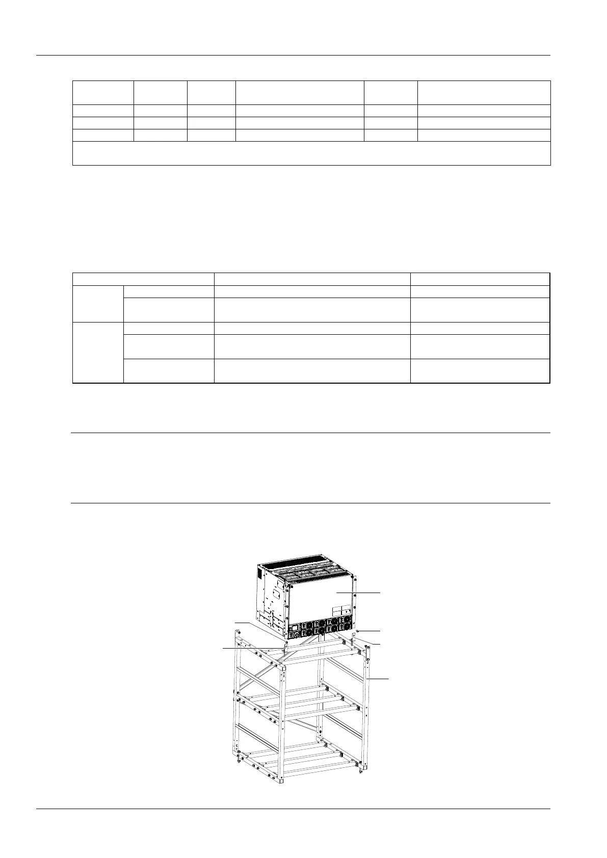
Installed on the battery rack
Fix the subrack power system to the battery rack through the connectors with M6 bolts, as show in Figure 2-1.
Power system
M6 screw
Connector
Battery rack
M6 screw
Connector
Figure 2-1 Cabinet and rack installation

 Loading...


