13
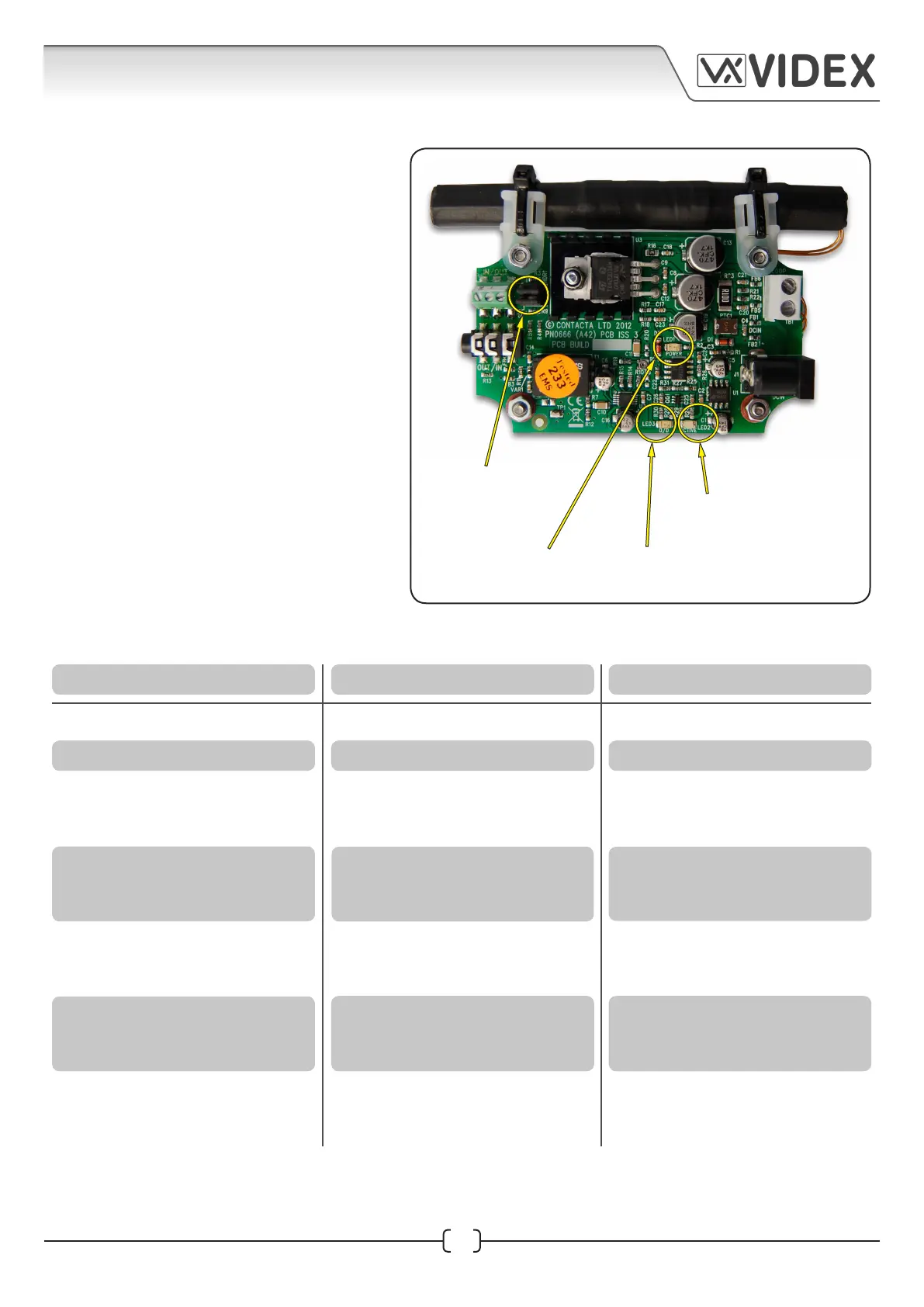
LED1: Power Indicator
LED2: Active Indicator
LED3: Overdrive Indicator
HDR1 Jumpers
(both jumpers
should be removed)
INDUCTION LOOP GUIDE
Induction Loop Guide EN-UK - V.1.1 - 19/10/16
Fig.24
TROUBLESHOOTING
INDUCTION LOOP OPERATION
The Induction Loop has been designed
to be left unattended once it has been
correctly installed and powered ON.
Fig.24 shows the onboard LED indicators:
LED1 - POWER: If this LED is constantly
lit (red) then this indicates there is 12Vdc
power to the Induction Loop.
LED2 - ACTIVE: If the induction loop is
being driven correctly then this LED
will illuminate (green) to indicate that a
steady signal is passing through.
LED3 - OVERDRIVE: If the audio signal
level increases through the induction
loop this LED will start to illuminate red
and get brighter in intensity. If it shows a
continuous red then the drive level is too
high and audio distortion will occur.
LED1 OFF
LED1 ON, Other LEDs OFF
LED1 ON
LED2 ickers or steady
LED3 ickers regularly
LED1 ON
LED2 steady
LED3 continuously ON
LED1 ON
LED2 ickering or steady
LED3 OFF or occasionally ickers
SYMPTOM POSSIBLE FAULT ACTION
PSU disconnected or failed Investigate power supply
No audio input Investigate audio connection
Normal operation
Correct operation, although
audio input could be low
No action required
Increase audio level if possible, try
turning up speaker POT on audio
amplier
LED1 ON
LED2 OFF
LED3 continuously ON
Excessive audio input. Danger of
distortion or overheating
Induction Loop disconnected,
open circuit or incorrect
specication
Reduce audio level, try turning
down speaker POT on audio
amplier
Investigate Induction Loop and
its connections, check connected
to audio amplier correctly
Interference (buzzing, whistling
or hissing) is heard through
Induction Loop
Unscreened or poorly earthed 3rd party
equipment is being used or in close
proximity, incorrect PSU being used
Switch o 3rd party equipment
to identify the source of
interference
 Loading...