6
INDUCTION LOOP GUIDE
Induction Loop Guide EN-UK - V.1.1 - 19/10/16
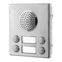
CONNECTING TO A 4K SERIES SPEAKER MODULE
In the following example an Art.4836 speaker is used. The instructions below can be followed when
fitting the Induction Loop to any of the 4K series speaker (and camera) modules including the digital
Art.4202 series and Art.4212 series speakers as described on page 3.
1. First ensure that any power connections are
disconnected from the 4K series speaker
module and disconnect any other wires
from the speaker terminals.
2. If it hasn’t already been done, remove the
4K series speaker module from the front
support frame.
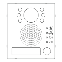
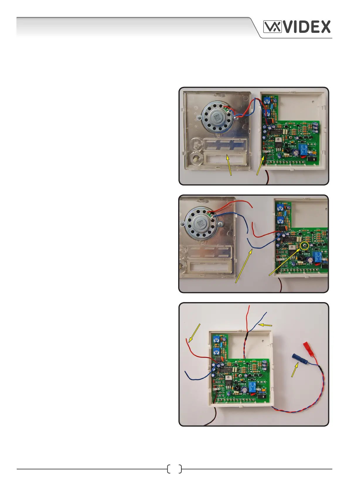
3. Unclip the front metal speaker fascia from
the module’s back plastic, as shown in Fig.1.
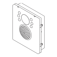
4. Take a pair of wire cutters and cut the Red
and Blue speaker wires, as shown in Fig.2.
5. Unscrew the pcb screw in the middle of the
speaker pcb in order to manoeuvre the pcb
inside the back plastic (do not remove the
pcb), refer to Fig.2.
6. Take the Red/Blue female connector cable
and feed it through the underside of the
speaker pcb, coming in from the right hand
side of the speaker terminals (the ends of
the Red and Blue wires will eventually come
out at the top end of the pcb) as shown in
Fig.3.
7. Take one of the Scotchlok™ 3 way butt
connectors with the transparent side facing
up.
8. Next take the Red wires from the speaker
and the speaker pcb and the red wire from
the Red/Blue female connector cable. Feed
each wire, in turn, into one of the connector
barrels on the Scotchlok™ 3 way butt
connector, as shown in Fig.4. (When feeding
the red wires into the Scotchlok™ 3 way butt
connector they should be pushed all the way
to the end of the connector as far as they will
go, this can be seen through the transparent
side of the connector).
Fig.1
Fig.2
Fig.3
cut both speaker wires
unclip front fascia from back plastic
red/blue wires from
the female bullet cable
fed up through the
underside of the pcb
female bullet
connectors
speaker pcb wires
pcb screw
 Loading...