7602026
18
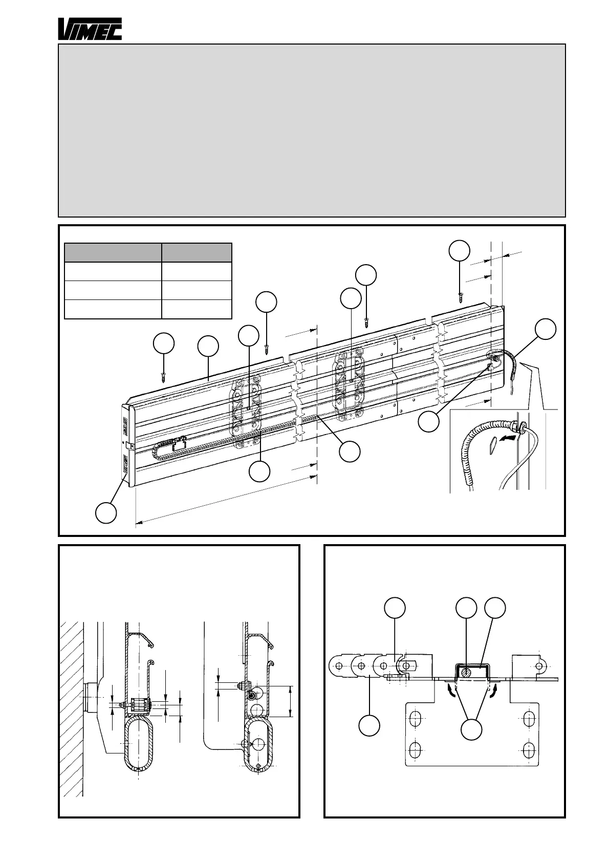
ONLY FOR STOCK GUIDE:
- Holding to the specific dimensions (Fig. 9) for each equipment, proceed to the drilling of the chain
holder profile (aluminium bonnet - Fig. 10).
- Assemble the terminal mesh (Fig. 11/a) to the cable carriage chain (Fig. 11/b) and fix it to the support.
The cable (Fig. 11/c) must be placed with the protection guard (plus its seal - Fig. 11/d) bending the two
tongues (Fig. 11/e).
- Insert the cable carriage chain (Fig. 9/a) and fix it with the indicated screw TSPCE M4x45, washer 6x18
and self-locking nut M4. Fix the cable-stopper clamp (Fig. 9/b) with the indicated screw TE M6x14 and
self-locking nut M6.
- Assemble and fix the telescoping plate (Fig. 9/f) with self-tapping screws 4.8x13 (Fig. 9/g).
- Assemble and fix the cable guide profile.
- Assemble the guard and the cover with the indicated self-threading screws 4.8x13, on the guide lower
side (Fig. 9/d).
FIG.9
SECTION A-A SECTION B-B
Guide lenght Dimension A
from 1500 to 3300
from 3300 to 6900
from 6900 to 14100
1400
3200
6800
FIG.10 FIG.11
40
Ø 7
15
Ø 10
Ø 5
a
b
c d
e
A
LOW SIDE
A
A
d
c
f
g
g
g
a
g
HIGH SIDE
B
B
b
a
c
8
0
e
 Loading...


