14 15
T40
ONLY
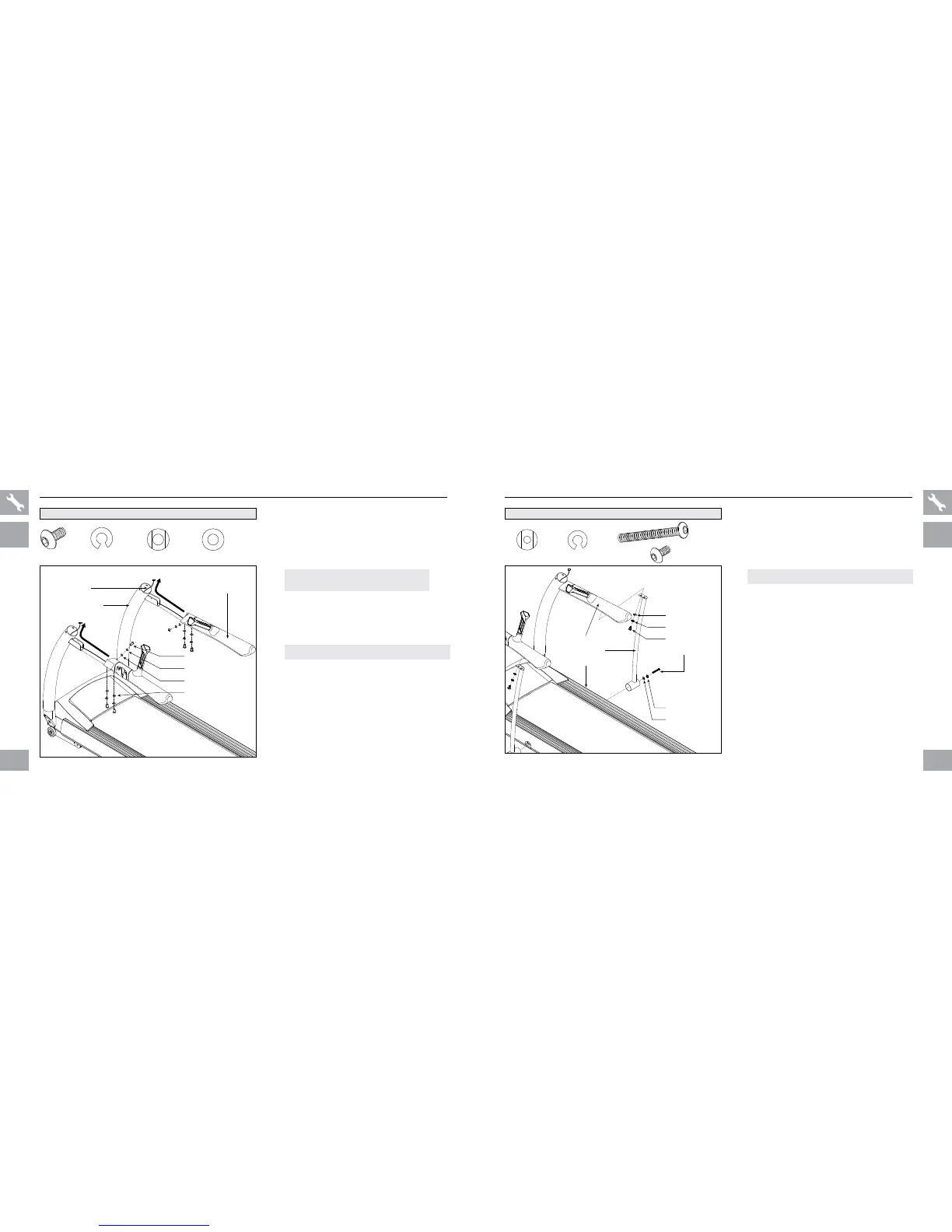
T40 ASSEMBLY STEP 3
BOLT (A)
SPRING WASHER (B)
BOLT (F)
HANDLEBAR
SUPPORT BAR
BASE FRAME
ARC WASHER (E)
SPRING WASHER (B)
ARC WASHER (E)
T40 HARDWARE FOR STEP 3 :
NOTE: This step is for T40 models only.
A Open hardware for step 3.
B Attach the right support bar to the base
frame using 1 arc washer (e), 1 spring
washer (b) and 1 bolt (f).
NOTE: Do not tighten bolts until step 4 is complete.
C
Attach the right support bar to the
handlebar using 1 arc washer (e), 1
spring washer (b) and 1 bolt (a).
D Repeat on other side.
BOLT (A)
20 mm
Qty: 2
SPRI NG
WASHER (B)
8.2 mm
Qty: 4
ARC
WASHER (E)
8.4 mm
Qty: 4
BOLT (F)
95 mm
Qty: 2
ASSEMBLY STEP 2
BOLT (A)
20 mm
Qty: 6
SPRI NG
WASHER (B)
8.2 mm
Qty: 6
ARC
WASHER (C)
8.4 mm
Qty: 4
FLAT
WASHER (D)
8.2 mm
Qty: 2
HARDWARE FOR STEP 2 :
FLAT WASHER (D)
SPRING WASHER (B)
ARC WASHERS (C)
BOLT (A)
RIGHT HANDLEBAR
CONSOLE CABLES
RIGHT CONSOLE MAST
A Open hardware for step 2.
B Guide console cables from handlebars
through and out of the tops of the console
masts.
C Slide handlebars onto console masts.
D Attach right handlebar to right console
mast using 1 flat washer (d), 1 spring
washer (b) and 1 bolt (a) from the inside and
2 arc washers (c), 2 spring washers (b)
and 2 bolts (a) from below.
E
Repeat on other side.
NOTE: Do not pinch console cables while
attaching the handlebars.
T40 SHOWN
ALL
MODELS
T40 ONLY
NOTE: Do not tighten bolts until step 4 is complete.
 Loading...