15
Installation
· Velocity in delivery pipe: 2 to 3 m/s.
· Velocity in suction pipe: 1 to 2 m/s.
To avoid pump cavitation the NPSH available from the suction piping system must be higher than the NPSH required by the
pump. NPSH required by the pump. This is achieved by lowering the head loss of the suction piping, increasing its diameter,
minimum possible length, minimum number of fittings, not exceeding the required flow rate, low temperature (minus 33ºC if
water), minimum negative head and even better if the suction is positive.
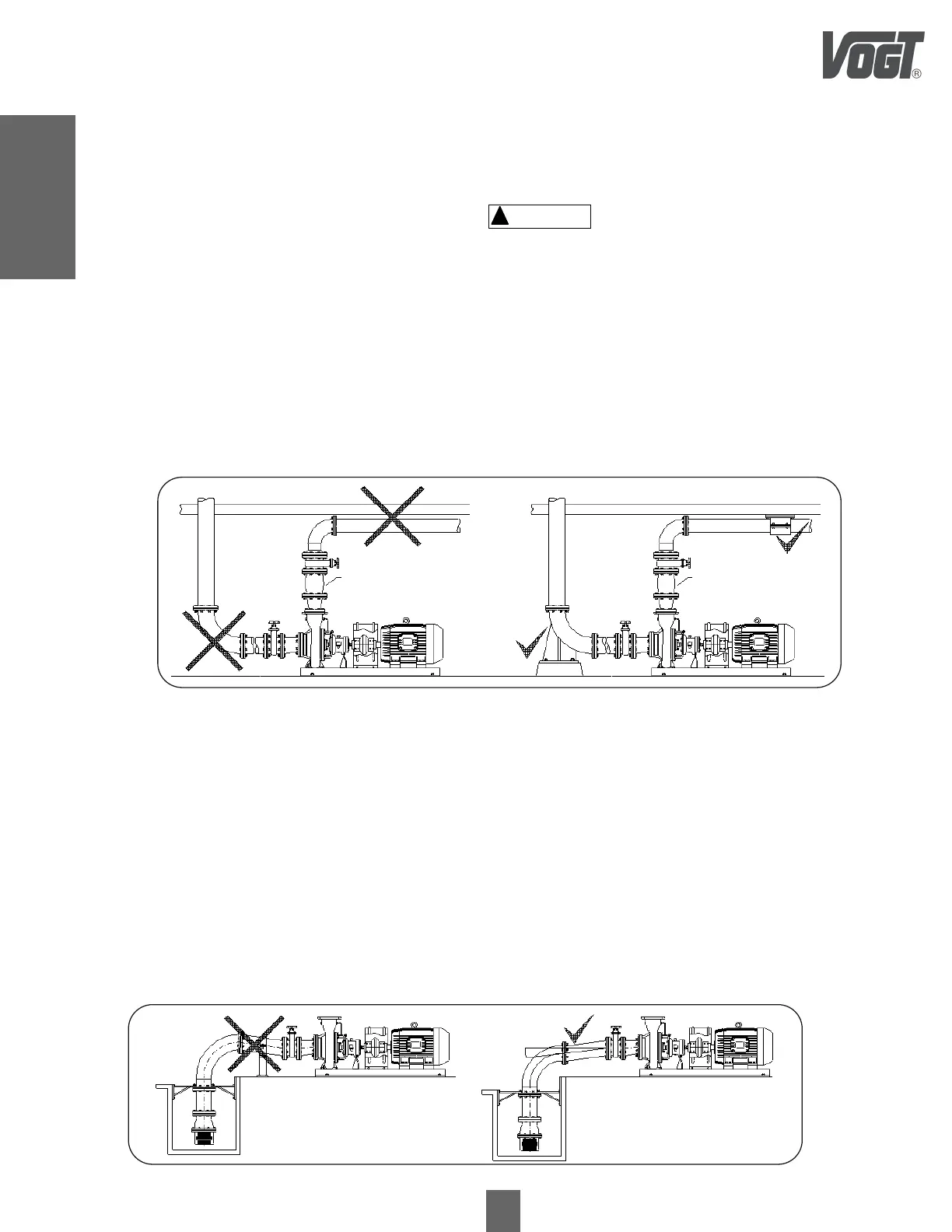
If a long suction line is required, it must be installed with a continuous elevation slope in the direction of the pump and
without high points, to avoid the accumulation of air pockets, see figure 9.
Installation
5.5 Joints to Rigid Pipe System
For optimum operation of the motor-pump equipment, the piping should not exert stresses on the equipment. The
equipment can be deformed, broken or misaligned, when the piping is not aligned with the axes corresponding to the
suction and discharge of the pump. The position of the suction and discharge ports must be totally parallel and with their
axes concentric to the pipes, in order to minimize stresses in the pump necks that deform it or produce a misalignment of
the axes. Do not forget to place gaskets between the joints.
Do not use the pump as a fastening point for the installation. The suction and delivery piping must not produce stresses on
the suction and discharge ports of the pump that may exceed their maximum values. The pipes must be fixed to the walls
or floors of the pump room in such a way that the pump is not subjected to their weight, see figure 8.
! CAUTION
Figura Figure 8
The diameters of pipes, valves and fittings should be calculated according to the expected head losses in the installation
and the following fluid velocities are recommended:
Figure 9
CHECK VALVE CHECK VALVE
 Loading...