16
Installation
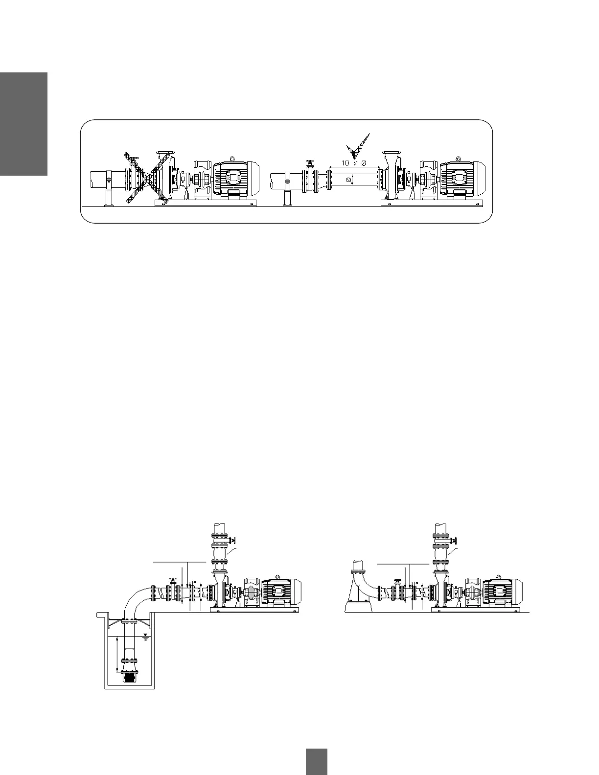
Figure 10
Installation
If a reduction is installed in the suction line, it must be eccentric and its straight part must be at the top, to facilitate the exit of
trapped air bubbles to the pump, see figure 9.
The elbows and fittings installed in the pump suction must be selected and installed in such a way that the liquid enters the
impeller in a symmetrical and orderly manner, this is achieved by installing a section of pipe of the same diameter as the
pump suction and a length of 10 times that diameter, see figure 10.
The end of the suction pipe, which goes at the source of the fluid, must be submerged at least 4 times its diameter to avoid
the formation of vortices, which cause air to pass into the pump and cut off the liquid flow, see figure 10.
After the suction and discharge pipes have been installed, they should be cleaned of any debris before starting up the
equipment, in order to avoid damage to the pump and other equipment installed in the system.
It is advisable to use a suction strainer in the suction pipe, amply dimensioned to prevent the entry of dirt larger than the size
allowed by the pump. Avoid sharp bends and fittings that narrow or widen abruptly (cones, valves, etc.).
The discharge pipe should generally have a larger diameter than the pump outlet. A gate valve should also be fitted to
regulate the flow rate and prevent possible overloading of the motor, as well as to isolate the pump during maintenance. To
avoid reverse rotation of the pumps (danger of unscrewing the impeller) a check valve (with by-pass if there is a foot valve)
should be placed in the delivery pipe.
If the pump is in negative suction, the suction pipe must be absolutely watertight and always rising towards the pump, with a
diameter generally larger than the pump outlet. The diffuser cone for the adaptation should be eccentric with the upper part
horizontal. Check that, at the normal working point, the NPSH required by the pump is at least 0.5 m lower than the available
NPSH of the installation. To prevent the pump from overpriming at a standstill, a foot valve should be placed at the end of the
suction pipe. It is recommended that the length of the cone diffusers be at least 7 times the difference of the nominal
diameters of the inlet and outlet of the cone, see figure 11.
CHECK VALVE
Lc=7x(Ø1-Ø2)
Lc=7x(Ø1-Ø2)
Ø1
Ø2
Ø1
Ø2
Ø
Ø
Ø
4 x Ø
CHECK VALVE
Figure 11
If the pump sucks under load, the suction pipe must be watertight and with a diameter generally larger than the pump
mouth. The diffuser cone can be eccentric or concentric. Install a gate valve for isolation during maintenance, see figure 11.
 Loading...