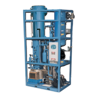
10TA Service Manual
HOW YOUR TUBE-ICE MACHINE WORKS
7/1/2014
4-1
4. How Your Tube-Ice
®
Machine Works
Principle Of Operation. For a detailed description of the functions of each control panel
components, see Section 6. Operation of the machine is controlled by “Clean/Off/Ice”, “Start” and
“Stop” switches located in the control panel of the freezing unit. Automatic operation can be
controlled by optional ice bin thermostats which will automatically stop and start the ice maker by
the level of the ice in the storage bin (NOTE: See “Ice Bin Thermostat Typical Installation” for
instructions on installation of the control bulb of the ice bin thermostat, FIGURE 3-8). The type ice
produced (cylinder or crushed) is determined by how the machine cutter is set-up (cylinder is
standard, crushed is optional). The control wiring is arranged so that the unit will stop only upon the
completion of a thawing period whether by action of the “Clean/Off/Ice” switch or the ice bin
thermostat.
The “Clean/Off/Ice” switch must always be set in the “Ice” position during normal ice-making
operation. It is set in the “Clean” position only when the equipment is to be cleaned as outlined in
the “Cleaning Procedure”, Section 7 and instructions attached to the machine.
If it should become necessary to instantly stop the machine, push the “Stop” button. To restart the
machine, push the “Start” button.
FIGURES 4-1 & 4-2 illustrate the piping diagram of the refrigerant and water circuits of the Tube-
Ice
®
machines with numbers for easy reference. Throughout this manual, the numbers you see in
parentheses refer to the numbers in this piping schematic.
The freezer (2) is a shell and tube-type vessel. During the freezing period, water is constantly
recirculated through the vertical tubes of the freezer by a centrifugal pump (6). Make-up water is
maintained by a float valve (12) in the water tank (7). Solenoid valve (20), sometimes referred to as
the “A” valve, is open and solenoid valve (18), sometimes referred to as the “D” valve, is closed.
Refrigerant gas from the top of the freezer (2) passes through the suction accumulator (88), the heat
exchanger (13), and to the compressor (3). Here the cool gas is compressed to a high temperature,
high pressure gas which discharges through the oil separator (14) and into the condenser (15). In the
condenser, heat is removed and the gas is condensed to a high temperature, high pressure liquid.
The high pressure liquid goes through the accumulator boil out coil (88) and suction line heat
exchanger (13) where it is gives up heat to the suction gas for compressor protection. In addition,
this liquid is subcooled and carried to the receiver (15R). Condensed liquid refrigerant from the
receiver flows through the thawing chamber (16) of the freezer, the filter/drier (46), the “A1” and
“A2” liquid feed valves (20) & (21) and then the expansion valve (17) and capillary. At the
expansion valve(17) and capillary feed, the refrigerant is taken from a saturated liquid state of
relatively high pressure and expanded to a very low pressure, low temperature liquid. The "A2"(21)
solenoid and capillary feeds liquid to the freezer (2) during the entire freeze cycle. The float switch
(22) is wired to the “A1” solenoid valve (20). The float switch energizes and de-energizes the “A1”
solenoid in response to the level of refrigerant in the freezer. The cold liquid refrigerant enters the
freezer where it absorbs heat from the circulating water. This cool gas is pulled out of the freezer at
the suction outlet thereby completing the circuit.
The freezing period is completed by action of the freezer pressure switch in the control panel. The
water pump (6) is stopped and solenoid valves “A1” & “A2” (20) & (21) are closed. The thawing
period then begins. Solenoid valve “D” (18) is opened, the cutter motor (5M) is started and the
harvest (thaw) timer is activated. Warm gas from the receiver is discharged into the freezer through
valve (18), thereby slightly thawing the outer edge of the ice which drops on the rotating cutter for
sizing. See “Freezer Period and Harvest Period” for more detailed description of operation.
 Loading...