10TA Service Manual
SERVICE OPERATIONS
4/28/14
9-16
Part No. 12A2110P0907
(Unloader Valve & 240V Coil)
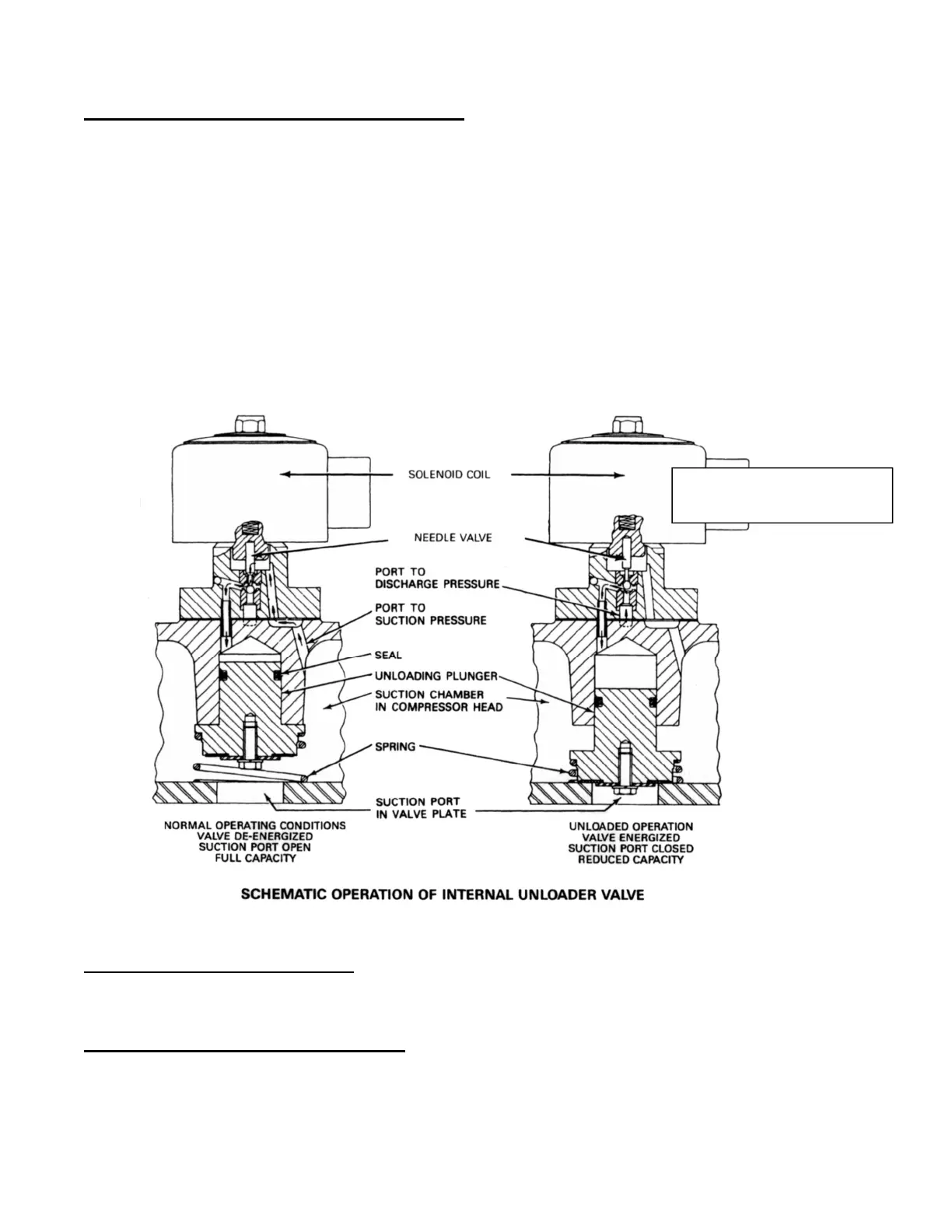
Capacity Control Valve (Internal Construction) A schematic illustration of the internal valve
operation is shown in FIGURE 9-11. (Part No. 12A2110P0907)
In the normal (full capacity) operating position with the solenoid valve de-energized, the needle
valve is seated on the lower port, and the unloading plunger chamber is exposed to suction pressure
through the suction port. Since the face of the plunger is open to the suction chamber, the gas
pressures across the plunger are equalized, and the plunger is held in the open position by the spring.
When the solenoid valve is energized, the needle valve is seated on the upper port, and the unloading
plunger chamber is exposed to discharge pressure through the discharge pressure port. The
differential between discharge and suction pressure forces the plunger down, sealing the suction port
in the valve plate, thus preventing the entrance of suction vapor into the unloaded cylinders.
The seal on the unloading plunger minimizes any leakage in pressure so that a pumpdown cycle may
be used with the valve either energized or de-energized without excessive compressor cycling.
FIGURE 9-11
Copeland Compressor Unloader Valve
Loaded Operation (during freeze) This capacity control valve is controlled by an electric solenoid.
When the solenoid is de-energized, the valve loads the cylinder bank (2 cylinders) as shown in the
above figure.
Unloaded Operation (during thaw only) During the thaw cycle, the solenoid coil is energized. The
needle valve is seated on the upper port, and the unloading plunger chamber is exposed to discharge
pressure through the discharge pressure port. The differential between discharge and suction pressure
forces the plunger down, sealing the suction port in the valve plate, thus preventing the entrance of
suction vapor into the unloaded cylinders.
 Loading...