63
Wiring diagrams
This section does not include wiring diagrams for the TAMD162C and TAMD163A engine with classifiable
electrical system. For more information refer to the manual “Electrical systems, Function and installation”.
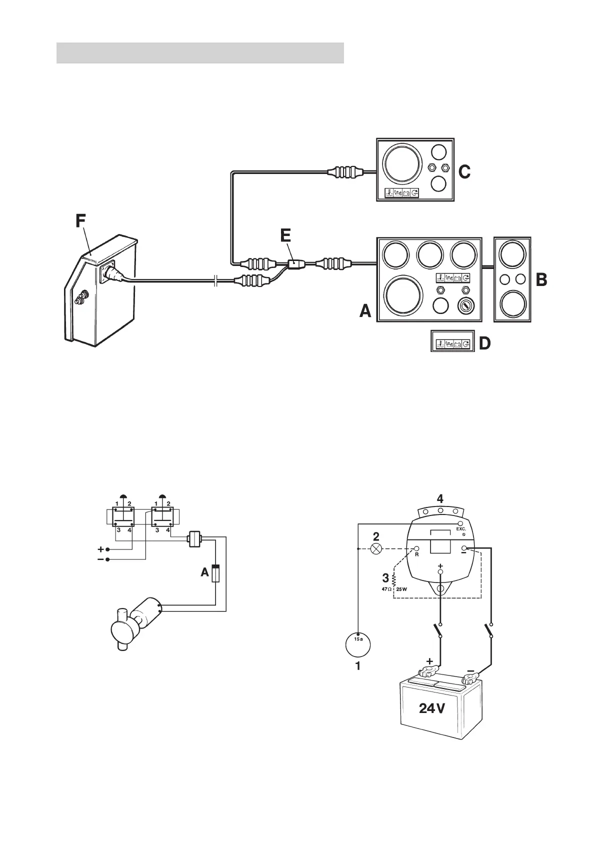
Block diagram
1. Key switch
2. Charge warning lamp
3. Resistance (47Ω/25W, P/N 863400-8)
4. Generator (GEN)
Extra generator 28V/100AOil scavenging pump
Suggested connection of oil scanvenger pump (pump-
ing and filling)
Cable area 1. 5mm
2
A. Fuse (8A)
A. Main panel
B. Auxiliary panel
C. Control panel for auxiliary control position (Flying Bridge)
D. Alarm panel (Used only when there is no main panel A)
E. Y connection
F. Electronics Terminal box
 Loading...