Maintenance: Electrical component diagrams
58
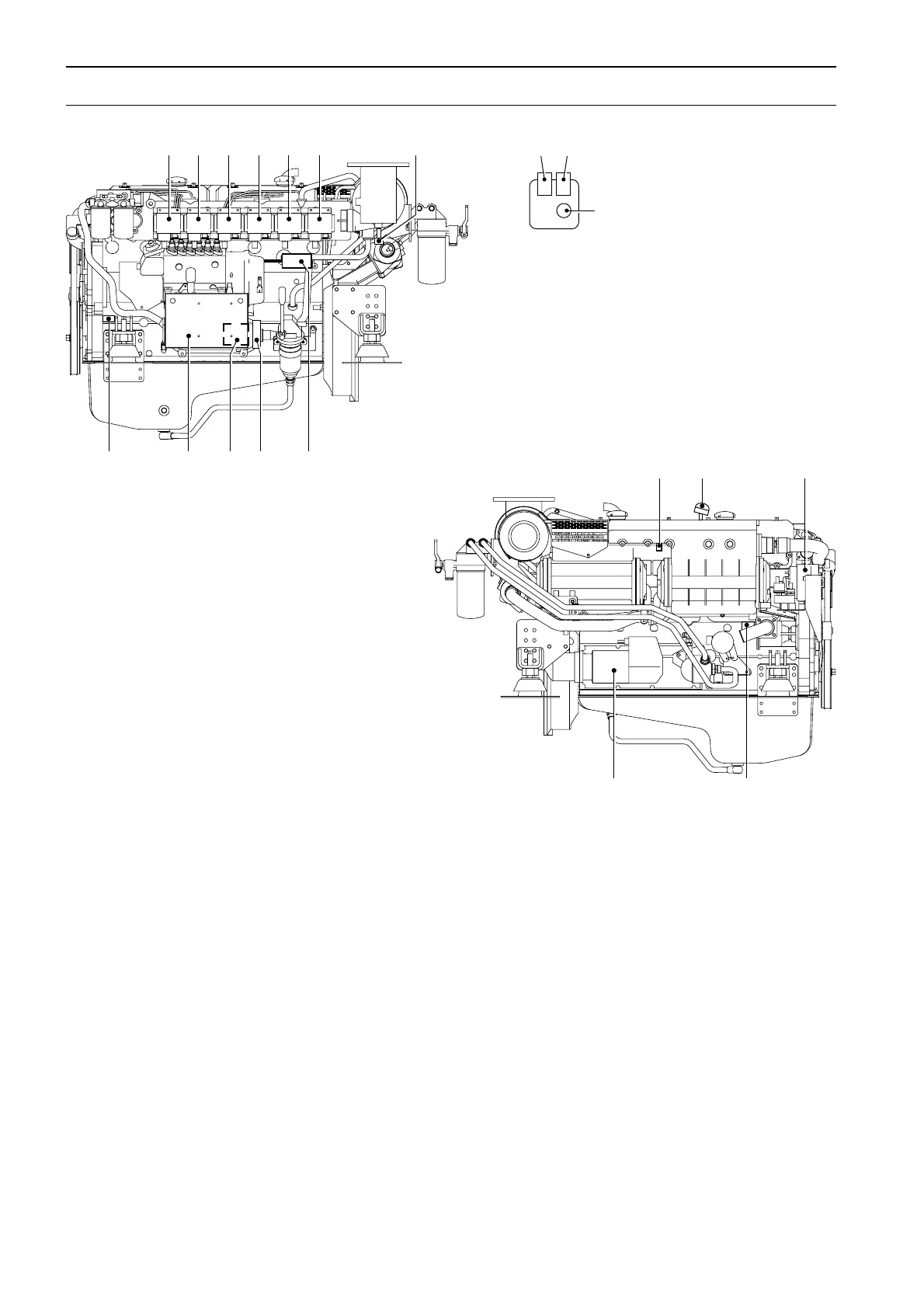
Electrical component diagrams
TAMD74A-A, TAMD74A-B
1. High engine oil temperature switch (alarm)
2. High coolant temperature switch (automatic stop)*
3. Low coolant pressure switch (alarm)
4. Low oil pressure switch, engine (automatic stop)*
5. Lubricating oil pressure sensor/switch (alarm), engine
6. Low oil pressure sensor/switch, reverse gear
(automatic stop)*
6a. Oil pressure sensor/switch (alarm)
6b. Low oil pressure switch (automatic stop)*
6c. Connection for testing device
7. Exhaust temperature sensor
8. Stop solenoid (normal stop)
9. Fuel leakage switch (alarm)
10. Fuel shut-off valve (emergency stop/overspeed stop)
11. Electrical box with fuses (fuse strip with glass-tube
fuses (2 x 20A and 2 x 8A)
12. Engine speed (RPM) sensor/switch* (automatic stop)
13. Low coolant level switch (alarm)
14. Engine coolant temperature sensor/switch (alarm)
15. Alternator
16. Low seawater pressure switch (alarm)
17. Starter motor
18. Oil temperature sensor, reverse gear**
19. Oil pressure sensor, reverse gear**
* Engines with automatic stop function (optional).
** Fitted on the reverse gear, not shown (engines without auto-
matic stop function).
123456 7
12 11 10 9 8
6
6a 6b
6c
13 14 15
17 16
 Loading...