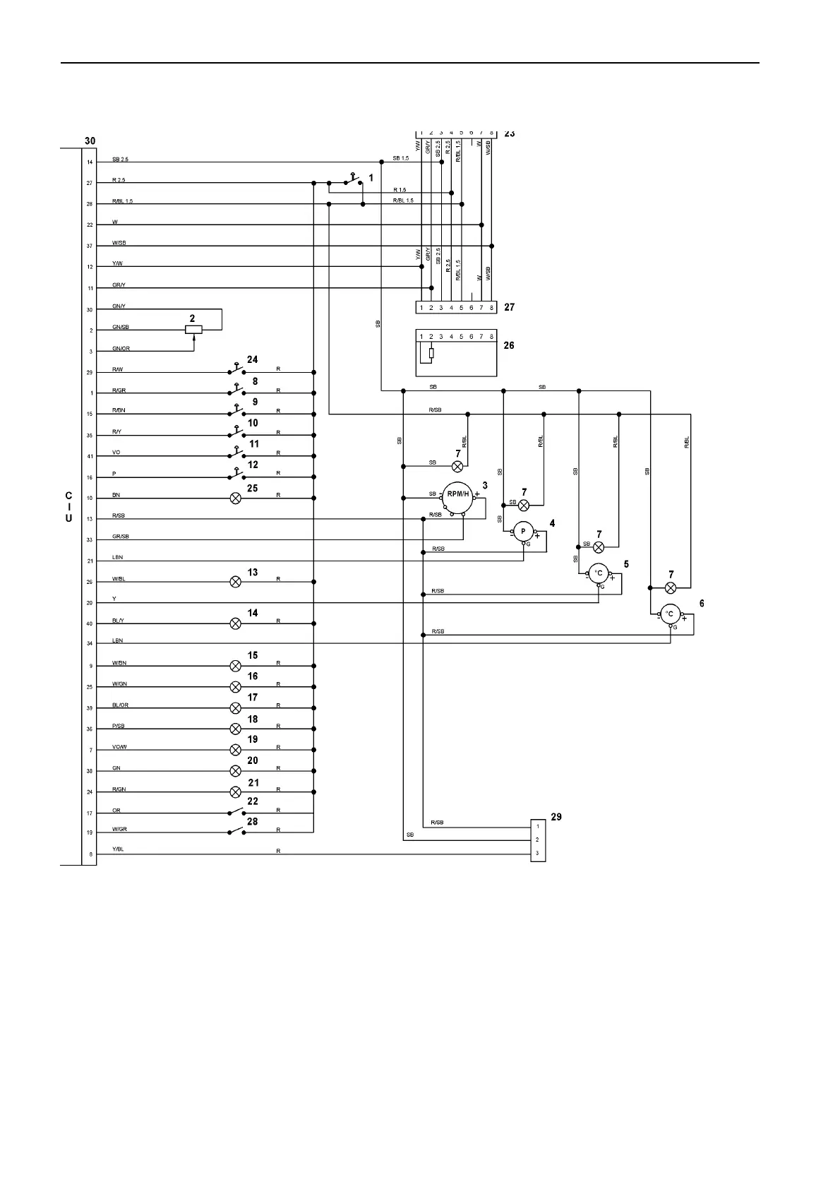
Wiring diagram Group 30: Electrical system
150
16. Alarm, low coolant level
17. Fuel alarm
18. Diagnostic lamp
19. Horn
20. Operation indicator
21. Preheating indication
22. Preheating contact
23. 8-pin connector engine interface
24. Governor switch
25. Battery voltage alarm
26. Termination resistance 120 Ohm
27. 8-pin connector engine interface
28. Contact, engine protection override
29. Easy Link connector block
30. Control Interface Unit (CIU)
CIU
Cable colors
BL = Blue
LBL = Light blue
BN = Brown
LBN = Light brown
GN = Green
GR = Grey
OR = Orange
P = Pink
R = Red
SB = Black
VO = Violet
W = White
Y = Yellow
Cable area = 0.75 mm
2
unless
otherwise specified.
1. Key switch (15+)
2. RPM potentiometer
3. Tachometer (code 14)
4. Oil pressure, instrument
5. Oil temperature, instrument
6. Coolant temperature, instrument
7. Instrument illumination
8. Idling contact, two-way
9. 1500 / 1800 rpm switch, two-way
10. Starter contact, spring biased
11. Stop switch, spring biased
12. Diagnosis contact, spring return
13. Alarm, low oil pressure
14. Alarm, high oil temperature
15. Alarm, high coolant temperature
 Loading...