of the oil contamination and replace the desiccant cartridge.
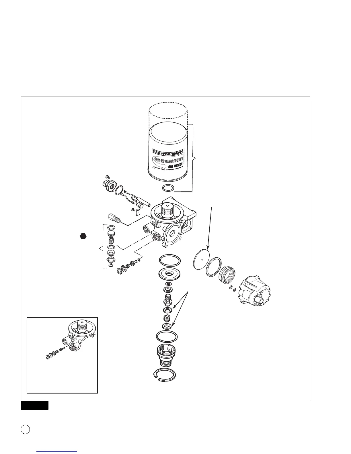
BYPASS VALVE
ASSEMBLY
Bypass valve is used on
dryers with date codes
earlier than 0894.
1002189a
O-Ring
Do not grease
diaphragm.
1200 Series air dryers do
not use bypass valve.
HEATER ASSEMBLY
• Disconnect plug.
• Remove old assembly.
• Install replacement element and
thermostat.
— Install retainer and screw to secure.
• Install replacement O-ring and receptacle.
— Fasten in place with screws.
Refer to Section 3 for more
detailed instructions.
DESICCANT CARTRIDGE
• Remove old cartridge.
• Lube and install O-ring.
• Install replacement cartridge.
T
PRESSURE RELIEF VALVE
• Unscrew and remove
old valve.
• Screw replacement
valve into dryer or
Street-Tee fitting.
• Do not exceed
recommended torque.
Refer to Pressure Relief
Valve in Section 3.
REGENERATION
VALVE ASSEMBLY —
REGENERATION STYLE
DRYERS ONLY
• Remove old assembly and
diaphragm.
• Clean diaphragm lip groove.
• Install replacement
diaphragm and assembly.
PURGE VALVE ASSEMBLY
• Remove old assembly.
• Clean valve bore.
• Grease valve bore.
• Install replacement assembly.
*
E Series dryers use a different style turbo
cut-off valve (Refer to Parts Book PB-96134).
**
Spring not used with U Series dryers.
NOTE: If shims are included in the
replacement kit, install one above
and one below the spring.
OUTLET CHECK
VALVE ASSEMBLY
• Remove old
assembly.
• Clean valve bore.
• Install replacement
O-ring in bore.
Then, grease O-ring
and bore.
TURBO CUT-OFF
VALVE ASSEMBLY
*
• Remove snap ring.
• Use needle nose pliers
to remove the piston.
• Clean bore (if bore is
badly damaged,
replace the air dryer).
• Install replacement
assembly.
* *
1800
1200
SHIMS
(IF REQUIRED)
 Loading...