7 8
All rights reserved by WaydooAll rights reserved by Waydoo
Charging the PowerFlight Battery
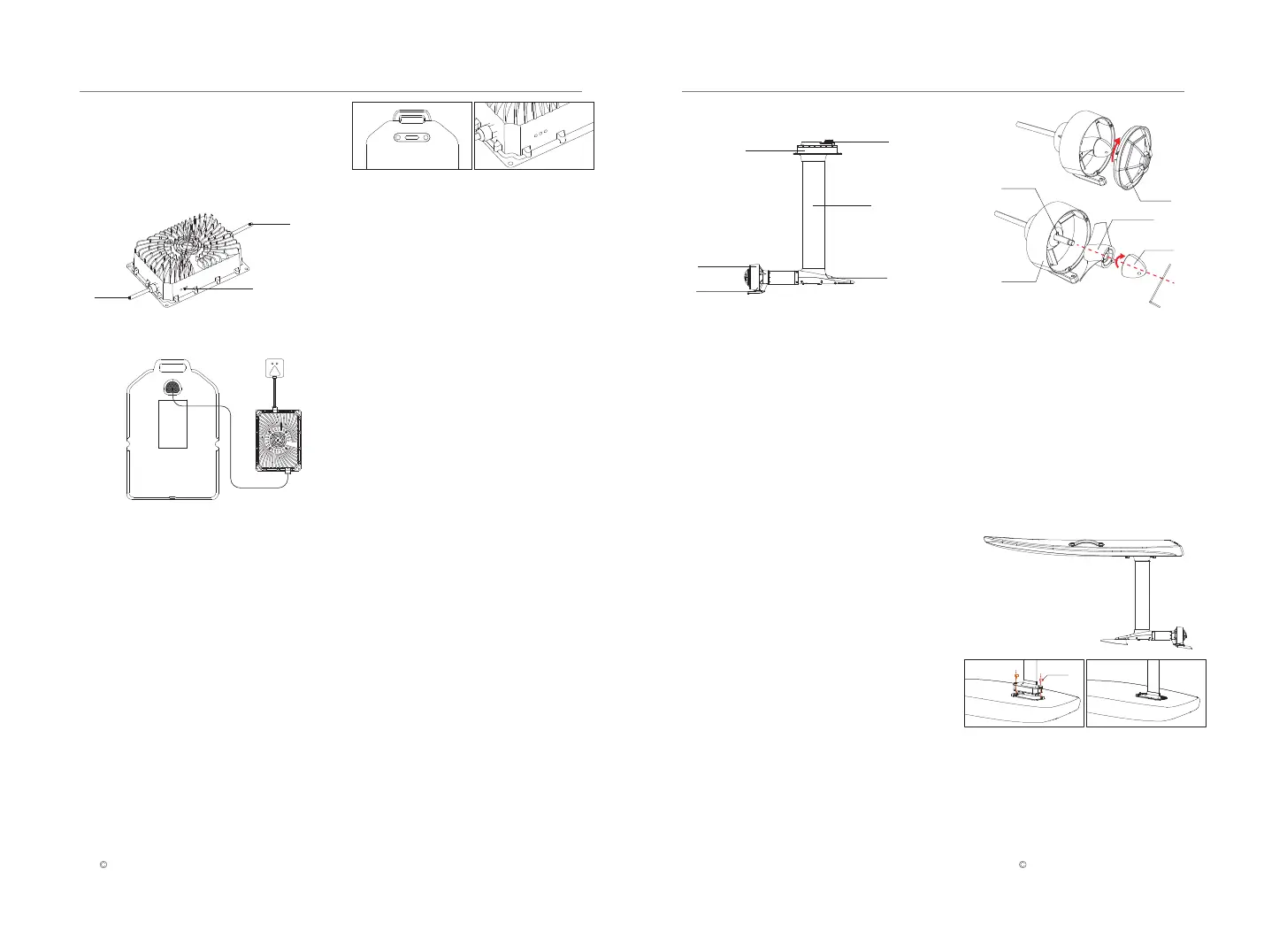
Waydoo Lithium Battery Charger
1. DC cable 2. AC Cord 3. Indicator
1
2
3
Adopting an aluminium alloy diecasting , the
Waydoo Lithium Battery Charger has an
input voltage of 100-240V, output voltage of
58.6V-58.8V, charging current of 16-17A, and
a protection level of IPX6.
Plus power kit is specially designed for Waydoo
Efoil products. It is compatible with both
standard board and premium board. The below
takes the standard board as an example to
explain how to install and use it.
7.When the Waydoo Lithium Battery Charger
indicator changes from flashing green to
steady green, it means that the PowerFlight
Battery charge fully. The PowerFlight Battery
usually takes 2 hours to charge fully. When
the indicator flashes red on the charger, it
means the PowerFlight Battery is malfunc-
tioning. Stop charging immediately if this
occurs.
If the battery will not be used in a short time, you
can start the healthy charging mode to extend
battery life for better usability. When the battery
power reaches 80%, it will automatically stop
charging.
Step
1. Press the battery power button four times
during the charging process.
2. The blue indicator light will flash back and
forth from the middle to the end.
3. The healthy charging mode is activated.
Note: This healthy charging mode is valid for a
single time after activation.
Plus power kit is specially designed for
Waydoo Efoil products, integrating a
brushless motor, motor driver, propeller, main
control board, Bluetooth communication
modules, etc. With a waterproof and quick-in-
stallation design, the plus power kit can be
easily installed on Waydoo Efoil products with
L-shaped bolts. The front and stabilizer wing
can be installed on the corresponding mount
with special screws.
Standard combination
25.6-inch mast & explorer wing
31.5-inch mast & patroller wing
Users can freely select different front wings
and masts according to their needs.
If your propeller is damaged and needs to be
replaced, please follow the below steps to
replace it.
Tool: M4 Allen Screwdriver
1. Turn the propeller protective cover clockwise
to remove it from the propeller guard.
2. Remove the bullet. Unscrew it from the
motor shaft with an M4 Allen screwdriver, and
remove the current propeller.
3. Remove the current propeller pin and
replace it with a new pin. Insert the pin into the
cross hole located on the propeller shaft at the
motor output. Center the pin on the motor
shaft.
4. Reassemble the propeller: Take a new
propeller (confirming that it has no defects
such as deformation or scratches), and
assemble the propeller. Note that the direction
of the propeller groove should be consistent.
5. Reassemble the new bullet and the propeller
protective cover, and the propeller replace-
ment is done.
Healthy charging mode
Plus power kit
Propeller Replacement Steps
1.Place PowerFlight battery and charger in a
cool dry location away from flammable or
hot items.
2.Connect the charger's DC cable to the
battery's DC port, press firmly, but do not
force, to install it in place, and place the
battery face up on the hard ground.
3.Plug the AC cord into a wall outlet.
4.The charger power indicator shows a
steady blue light, indicating standby mode.
5.Short press the linking button on the
PowerFlight battery, and the indicator will
change from steady blue light to a flashing
blue light, waiting for communication.
6.When the fashing blue light turns to
flashing green, the battery is now charging.
Note: Risk of fire, explosion and/or burns,
including chemical burns. Inspect battery for
damage before charging and never charge
damaged battery, place near heat, or attempt
to open the battery casing.
1.DC Port
1. propeller protective cover
2. propeller 3. bullet 4. propeller pin
5. propeller guard
3.Mast Head 4.Support Rod
2.Front Wing Mount
5.Propeller Guard 6.Stabilizer Wing Mount
Collectively these components make up
the mast.
Assembly Steps
Please strictly follow the following installation steps.
(1). Assembling the Mast
1. Turn the Board over to insert the Plus power
kit vertically into the mast installation hub.
2. After inserting the mast head into the hub,
make sure it fits, fixes with L-shaped bolts and
tighten.
Note: Before installing, please make sure the
mast DC port is free of any water and debris.
(Clean and dry it if necessary)
1
3
2
4
5
L-shaped bolts
3
1
4
2
5
6
Explorer/Patroller PLUS Power Kit USER GUIDES Explorer/Patroller PLUS Power Kit USER GUIDES
 Loading...