Top fixture slide
(2) 1/4”-20
Flange hex nuts
Horizontal
track
Short stem
track roller
Top section
Intermediate
section
Top
section
Top
section
COUNTERBALANCE
INSTALLATION INSTRUCTIONS
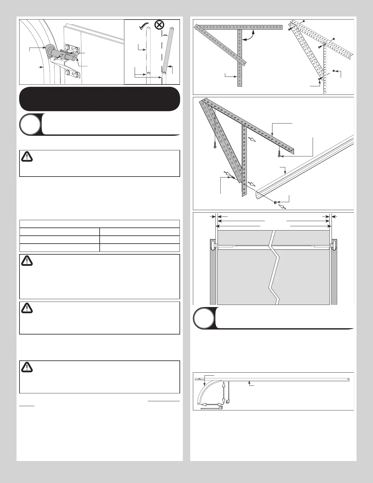
Attaching Rear Back Hangs
16
Raise the door until the top section and half of the next section are in the horizontal track
radius. Do not raise door any further since rear of horizontal tracks are not yet supported.
WARNING
RAISING DOOR INTO THE LOOSE HORIZONTAL TRACKS CAN RESULT IN
DOOR FALLING AND CAUSE SEVERE OR FATAL INJURY.
Clamp a pair of locking pliers onto the vertical tracks just above the second track roller on
one side, and just below the second track roller on the other side. This will prevent the door
from raising or lowering while installing the rear back hangs.
Using the chart below, select the appropriate perforated angle (may not be supplied). Fabri-
cate and install rear back hangs, as shown.
NOTE: If an opener is installed, position horizontal tracks one hole above level when securing
them to the rear back hangs.
Perforated Angle Gauge Weight Limitations For Extension Springs:
Perforated Angle Gauge Door Balance Weight
1-1/4” x 1-1/4” x 15 Gauge 220 lbs. to 440 lbs.
1-1/4” x 1-1/4” x 16 Gauge 175 lbs. to 350 lbs.
WARNING
MAKE SURE BACK HANGS ARE BRACED SUFFICIENTLY TO RESIST ANY
MOTION DURING SPRING APPLICATION AND DOOR TRAVEL. IF BACK
HANGS PIVOT OR DEFLECT, ADD REINFORCEMENT UNTIL THEY REMAIN
FIRM AND STATIONARY. ANY BACK HANG THAT HAS BENT MUST BE
REPLACED.
WARNING
KEEP HORIZONTAL TRACKS PARALLEL AND WITHIN 3/4” TO 7/8” FROM
DOOR EDGE, OTHERWISE DOOR COULD FALL, RESULTING IN SEVERE OR
FATAL INJURY.
IMPORTANT: DO NOT SUPPORT THE WEIGHT OF THE DOOR ON ANY PART OF THE REAR
BACK HANGS THAT CANTILEVERS 4” OR MORE BEYOND A SOUND FRAMING MEMBER.
NOTE: If rear back hangs are to be installed over drywall, use (2) 5/16” x 2” hex head lag
screws and make sure lag screws engage into solid structural lumber.
WARNING
FAILURE TO ASSEMBLE AND ATTACH REAR BACK HANGS PROPERLY
ACCORDING TO THE ABOVE INSTRUCTIONS MAY RESULT IN DOOR
FALLING WHEN RAISED, CAUSING SEVERE OR FATAL INJURY.
NOTE: Perforated angle must be attached to sound framing members and nails should not
be used.
90°
(3) 5/16”
Bolts and nuts
(3) 5/16” Bolts and
(3) 5/16” nuts
Perforated
angle
5/16” Hex nut
5/16”-18 x 1-1/4”
Hex bolt
Perforated angle bolted
using (2) 5/16” x 1-5/8”
hex head lag screws to
ceiling member and
parallel to door
Horizontal track
NOTE: Repeat the same
process for right hand side.
Horizontal tracks
Door edges
3/4” To 7/8”
3/4” To 7/8”
Attaching Front Cable Lift Sheaves
17
IF YOU HAVE 3” FRONT CABLE LIFT SHEAVE AND A 12” RADIUS HORIZONTAL TRACK:
Starting on the left hand side and using (1) 3/8” - 16 hex nut, secure the front cable lift
sheave to the 13/32” hole near the top of the flag angle, as shown.
IF YOU HAVE 3” OR 4” FRONT CABLE LIFT SHEAVE AND A 15” RADIUS HORIZONTAL
TRACK: Starting on the left hand side and using (1) 3/8” - 16 hex nut, secure the front cable
lift sheave to the first 13/32” hole in the horizontal angle, as shown.
Repeat the same process for the right hand side.
Horizontal track angle
11
 Loading...