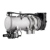
Unique to Thermo 90-ADR: For legal provisions relating to
the routing of the exhaust pipe refer to Technical Informa-
tion E3 - 5.10 (order no. 776 623).
Electrical Connections
Control Unit/Heater Connection
The electrical connection of the heaters is to be carried out
in accordance with circuit diagrams Figs. 16, 17, 18, 19, 20
and 21.
Connection upon the installation of Thermo 90 into a
vehicle for the transport of dangerous goods (ADR).
For legal provisions relating to the electrical connection
refer to Technical Information E3 - 5.10 (order no. 776
623).
The electrical connection is to be carried out in accord-
ance with circuit diagram Fig. 17.
NOTE:
Switch S6 must be so installed that upon the start-up of a
pumping device either positive or negative potential is ap-
plied to the respective inputs of the control unit.
Connection upon the installation of Thermo 90 S into a
vehicle for the transport of dangerous goods (ADR).
When installing the Thermo 90 S heaters in vehicles for
the transport of dangerous goods, the requirements laid
down in ADR 002 and ADR 003 (Technical Guidelines re-
lating to the directive concerning the carriage of dangerous
goods by road) must be fulfilled in addition to those of the
StVZO. The electrical connection is to be performed in ac-
cordance with circuit diagram Fig. 20 or 21.
NOTE:
Switch S7 must be installed in such a way that positive
potential is applied across the corresponding input of the
electronic control unit when a pumping device is put into
operation.
CAUTION:
If no ground connection is provided via Y2 or H5 when the
heater is activated, all ADR functions will be inoperative.
After positive potential has been applied across the X12/5
control unit input (auxiliary drive “ON”), a short 20-second
after-run period will follow and subsequently the control
unit will be in the ’fault lock-out’ state.
CAUTION:
In accordance with the Technical Guidelines relating to the
ordinance concerning the carriage of dangerous goods by
road, heaters may only be activated by means of a special,
manually operated switch located in the driver’s cabin.
If the heater is equipped with a standard digital timer it
must be ensured that pin 4 of the timer remains unas-
signed so that the heater can only be activated by means
of the instant heat button (circuit diagram available upon re-
quest).
No other digital timers are allowed to be used in ADR ve-
hicles.
Connection of the Heater Controls
The heater can be switched on and off using the following
Webasto heater controls:
- Digital timer see circuit diagram Fig. 16, 18 or 19
- Switch see circuit diagram Fig. 17 or 20.
Vehicle Fan
The vehicle fan is activated by means of a relay, see cir-
cuit diagram Fig. 16, 17, 18, 19, 20 or by means of a relay
provided with an interior-temperature thermostat.
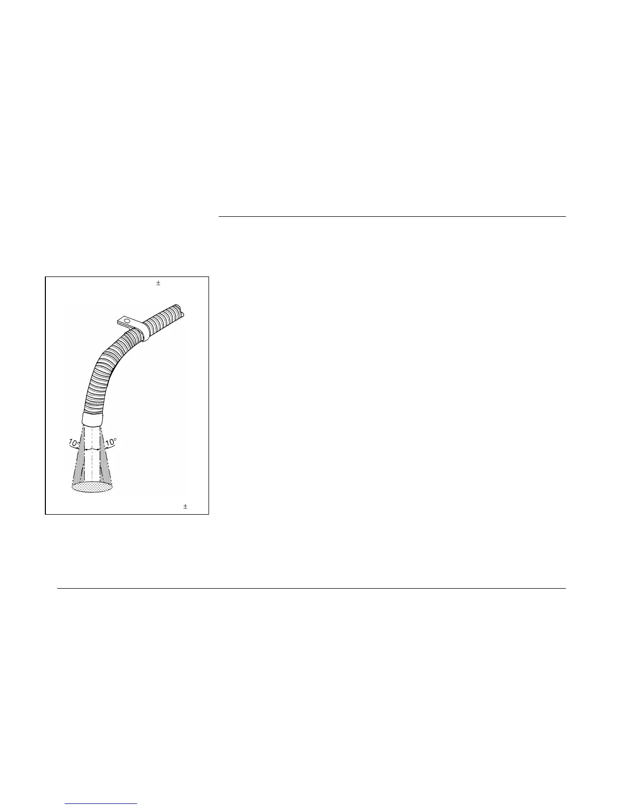
To ensure an angle of discharge of 90°
10°, it is re-
quired that the pipe clamp be attached no more than
150 mm, from the exhaust pipe end
direction of discharge approximately vertical 90°
10°
Fig. 13: Exhaust Pipe Discharge Opening
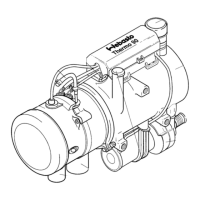
Installation Position
Thermo 90 / Thermo 90 S
8
 Loading...