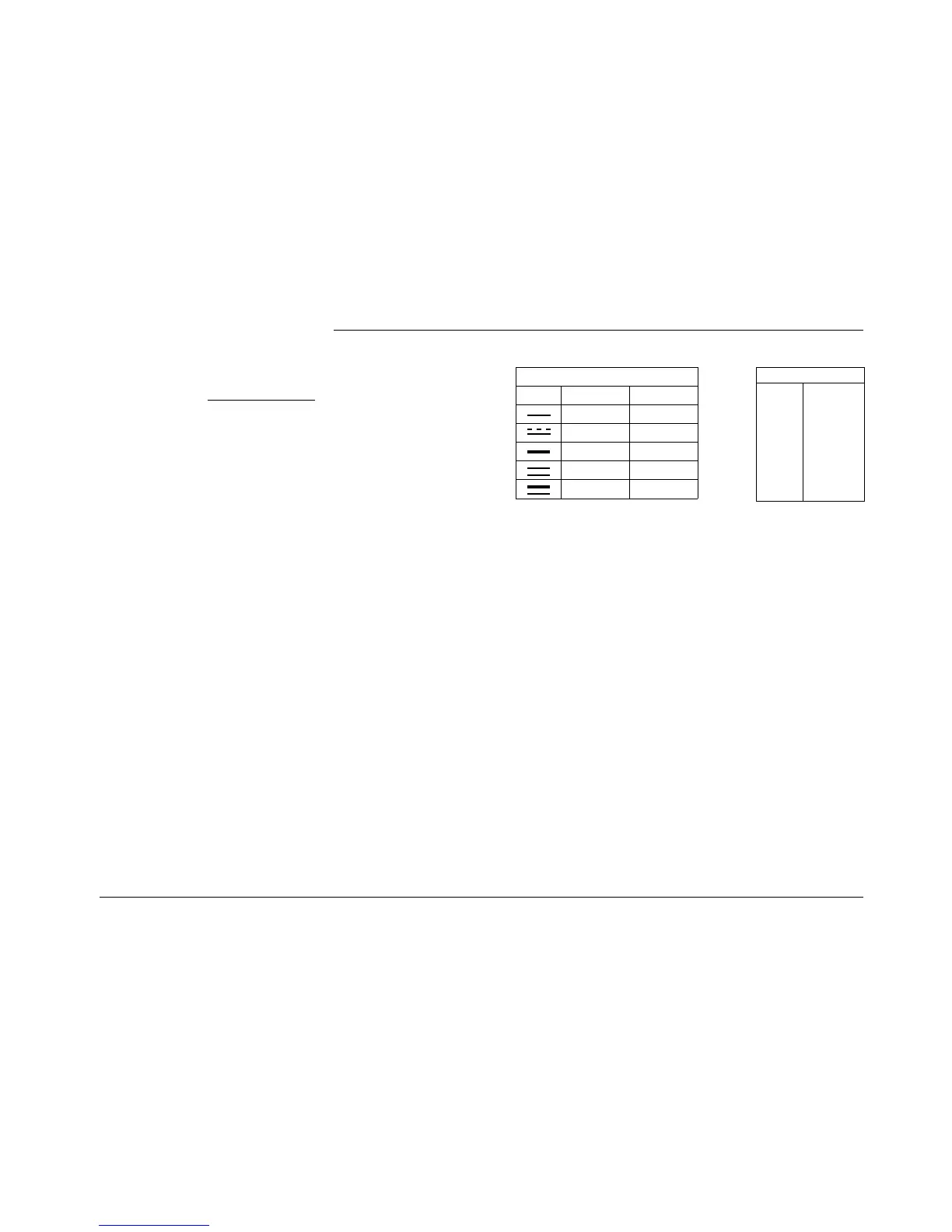
Legend for circuit diagrams:
➀ this terminal is not used for petrol-operated heaters.
➁ For temperature codification (temperature at water outlet) refer to the table on page 31
➂ Digital timer P1:
with positive voltage connected to pin 4 = continuous operation when “instant heat” is selected
positive voltage not connected to pin 4 = heating operation: 1 hour
➃ Digital timer P2:
with positive voltage connected to pin 10 = continuous operation when “instant heat” is selected
pin 10 open = variable heating times can be programmed
(10 min. to 120 min.); basic setting: 120 min.
Colour of cables
bl
br
ge
gn
gr
or
rt
sw
vi
ws
blue
brown
yellow
green
grey
orange
red
black
violet
white
Wire cross sections
< 7,5 m 7,5 - 15 m
0,75 mm
2
1,0 mm
2
1,0 mm
2
1,5 mm
2
1,5 mm
2
2,5 mm
2
2,5 mm
2
4,0 mm
2
4,0 mm
2
6,0 mm
2
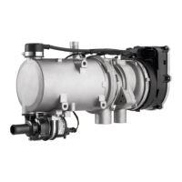
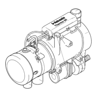
Thermo 90 / Thermo 90 S
10
 Loading...