Installation and Mounting
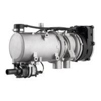
The metering pump is to be attached by vibration-damping
suspension. The installation position is restricted in accord-
ance with Figs. 10 and 11 in order to ensure sufficient self-
ventilation.
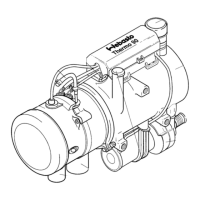
Fuel Filter
If dirt in the fuel must be reckoned with, only Webasto fil-
ter, order no. 487 171, should be used. Filter is preferably
to be installed in vertical position, where this is not
possible, it may also be installed horizontally (installation
position 0°-90°). Direction of flow to be observed!.
Combustion Air Supply
On no account must the combustion air be extracted from
areas where persons are present. The combustion air in-
take opening must not point in the direction of travel. It
must be so located that the possibility of clogging due to
contamination or snow and the drawing in of splash water
is remote.
The combustion air line (inside diameter min. 30 mm) may
have a length between 0.5m and 5m and may feature sev-
eral bends totalling 360°. The smallest bending radius is
45 mm.
The combustion air inlet must not be located above the ex-
haust gas outlet.
NOTE:
If it is not possible to route the combustion air line in a
downward pitch, a ø 4mm water drain hole is to be pro-
vided at the lowermost point.
When the heater is installed in the vicinity of the vehicle
tank in a common installation space, combustion air must
be drawn in from the outside of the vehicle and the ex-
haust gas be discharged to the atmosphere. Lead-through
openings must be splash-proof.
If the heater is located in an enclosed installation housing,
a ventilation opening of at least 6 cm
2
is required. If the
temperature in the installation housing exceeds the per-
missible ambient temperature of the heater (see Technical
Data), the ventilation opening must be enlarged after con-
sultation with Webasto.
Exhaust Pipe
The exhaust pipe (inside diameter 38 mm) can have a
length between 0.5m and 5 m and may feature several
bends (totalling 360°, smallest bending radius 85 mm). It is
mandatory to provide an exhaust silencer which is to be in-
stalled near the heater.
The discharge opening of the exhaust pipe must not point
in the direction of travel (see Fig. 13).
The exhaust pipe discharge opening must be so located
that any clogging caused by snow or mud is not to be ex-
pected.
Rigid pipes made of unalloyed or alloyed steel with a mini-
mum wall thickness of 1.0 mm or flexible tubes of alloyed
steel only are to be used as exhaust pipes. The exhaust
pipe is to be secured to the heater, e.g. by means of a
clamp. For further regulations refer to the Legal Provisions.
12-volts and 24-volts - Petrol and Diesel
preferably
15°-90°
Fig. 10: Metering Pump
Installation Position and Mounting
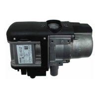
12-volts and 24-volts - Diesel only
Fig. 11: Metering Pump
Installation Position horizontal
0 - 90°
Fig. 12: Fuel Filter
Installation Position to be Observed
Thermo 90 / Thermo 90 S
7
 Loading...