If the heater is installed in vehicles equipped with injection
systems it is therefore to be determined whether the fuel
pump is mounted inside or outside the tank.
Where the fuel pump is located inside the tank, fuel may
only be extracted from the return line in which case it must
be ensured that the return line extends almost to the bot-
tom of the tank and that it is not closed by a nonreturn
valve. Failing this, the return pipe can be extended.
Where the fuel pump is mounted outside the tank, the con-
nection to the fuel system can be accomplished between
the fuel tank and the fuel pump.
Fuel Lines
Only steel, copper and plastic pipes made of plasticized,
light-resistant and temperature-stabilized PA 11 or PA 12
(e.g. Mecanyl RWTL) in accordance with DIN 73378 may
be used.
NOTE:
Do not cut Mecanyl lines using a side cutter.
As in the majority of cases it is not possible to route the
lines in a continuous upward pitch, the inside diameter
must not exceed a given dimension. If the inside diameter
equals or is greater than 4 mm, air or gas bubbles accumu-
late which result in malfunctions if the lines sag or are
routed in a downward pitch. When the diamters shown in
Fig. 4 and 8 are used, you can be sure that no unwanted
bubbles will form.
The lines leading from the metering pump to the heater
should not be routed in a downward pitch.
To prevent the fuel lines from sagging, freely suspended
lines must be secured. Mounting should be performed in
such a manner that the lines are protected against flying
stones and thermal influence (exhaust pipe).
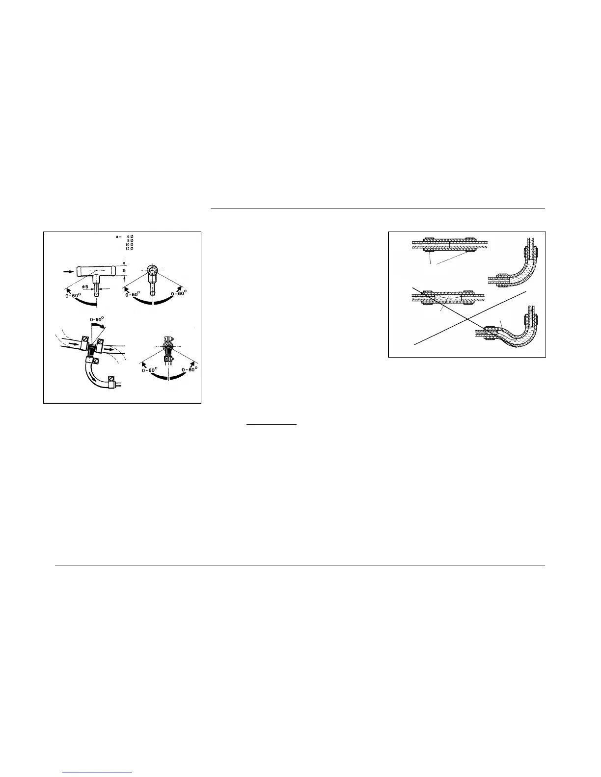
Connecting 2 Pipes Using a Hose
The proper connection of fuel lines using a hose is shown
in Fig. 9.
Check for leakage!
Metering Pump with Damper
The metering pump is a combined delivery/metering and
shutoff system and is subject to certain installation criteria
(see Figs. 4, 10 and 11).
Installation Location
Prior to installing the metering pump it must be ensured
that the maximum pressure prevailing at the fuel extraction
point is less than 0,2 bar.
It is recommended that the metering pump be installed in a
location which is sufficiently cool. On no account must the
permissible ambient temperature at any given operating
stage be in excess of + 20 °C in the case of petrol, and
+ 40°C in the case of Diesel variants.
Metering pump and fuel lines must not be located within
the radiation range of hot vehicle parts. If necessary, a radi-
ation protection is to be provided.
The preferred installation location is near the tank.
to metering pump
to engine
from tank
Fig. 8: Webasto Fuel Pickup
correct
incorrect
clamp
bubble
bubble
Fig. 9: Pipe/Hose Connection
Thermo 90 / Thermo 90 S
6
 Loading...