Electrical connections Thermo Top C / Thermo Top E
46
11 Electrical connections
11.1. Connection of control unit / heater
The electrical connections on the heater are made as shown in Fig. 17.
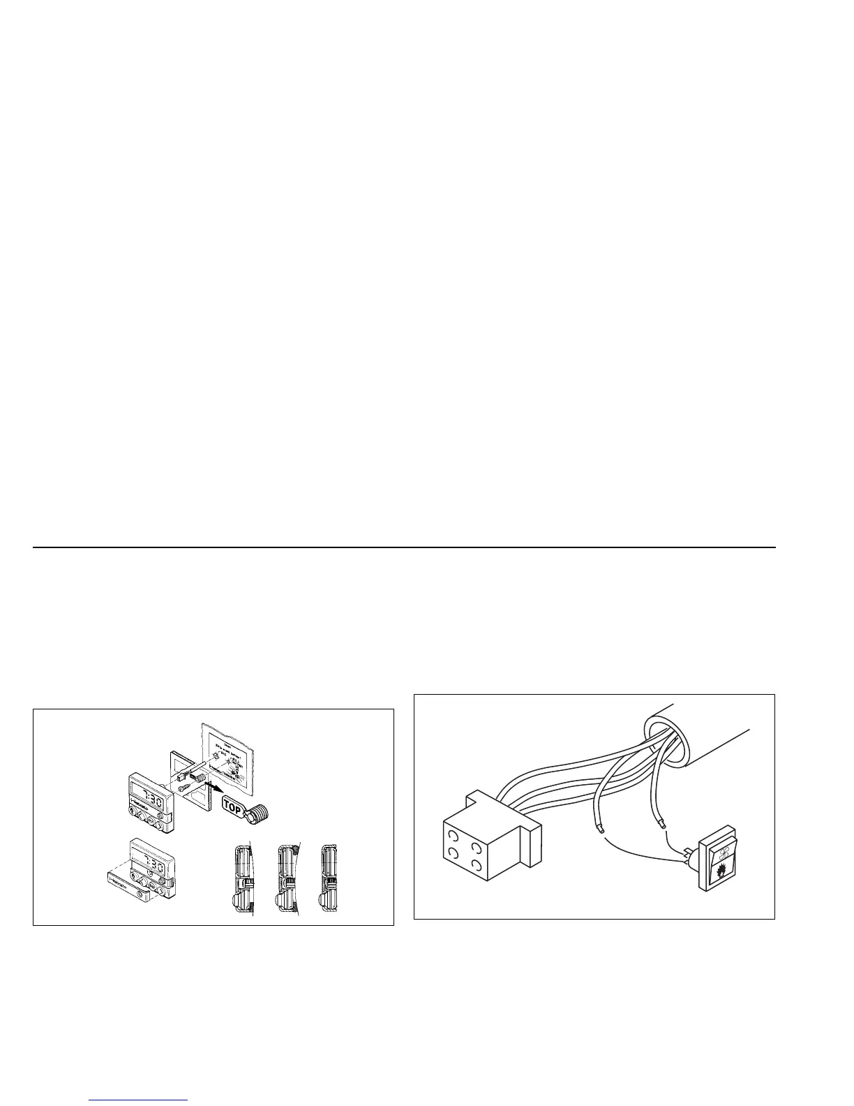
11.2. Installation and connection of the timer
The timer is installed as shown in Fig. 15. A drilling template is
enclosed.
The timer is connected as shown in the circuit diagram in Fig. 17.
NOTE:
Do not press on the display panel during installation.
11.3. Connection of the summer / winter switch (optional)
NOTE:
The summer / winter switch cannot be connected if the Telestart is
installed.
The summer / winter switch is connected as shown in Figs. 16 and 17.
NOTE:
The ends of lines br and vi are inserted in the insulating hose!
Fig. 15: Timer installation
Fig. 16: Connection of the summer / winter switch
Timer
connector
S5
br
vi
Strip
 Loading...