Section B - ComponentsJBE(X) Manual
Page 11
Scanner
The scanner is mounted to a sight tube that extends
past the face of the diffuser (approximately 1/8“)
where it can detect the pilot or main ame. This
location insures that it does not see the spark of the
pilot or reection off the refractory. The inside surface
of the scanner tube must be kept clean to prevent it
from absorbing the light and preventing the scanner
from detecting the ame.
Pilot
The pilot (Figure E-5) is positioned behind the
diffuser, so that the pilot ame passes through the
diffuser to ignite the main ame. It is located close to
the scanner tube, in the upstream direction to cause
the ame to pass in front of the scanner tube.
The pilot is connected to a gas pipe that extends
through the backplate in the burner drawer and can
be adjusted by moving the tube in the backplate. The
electrode is mounted to the venturi casting.
4. Gas Fuel Components
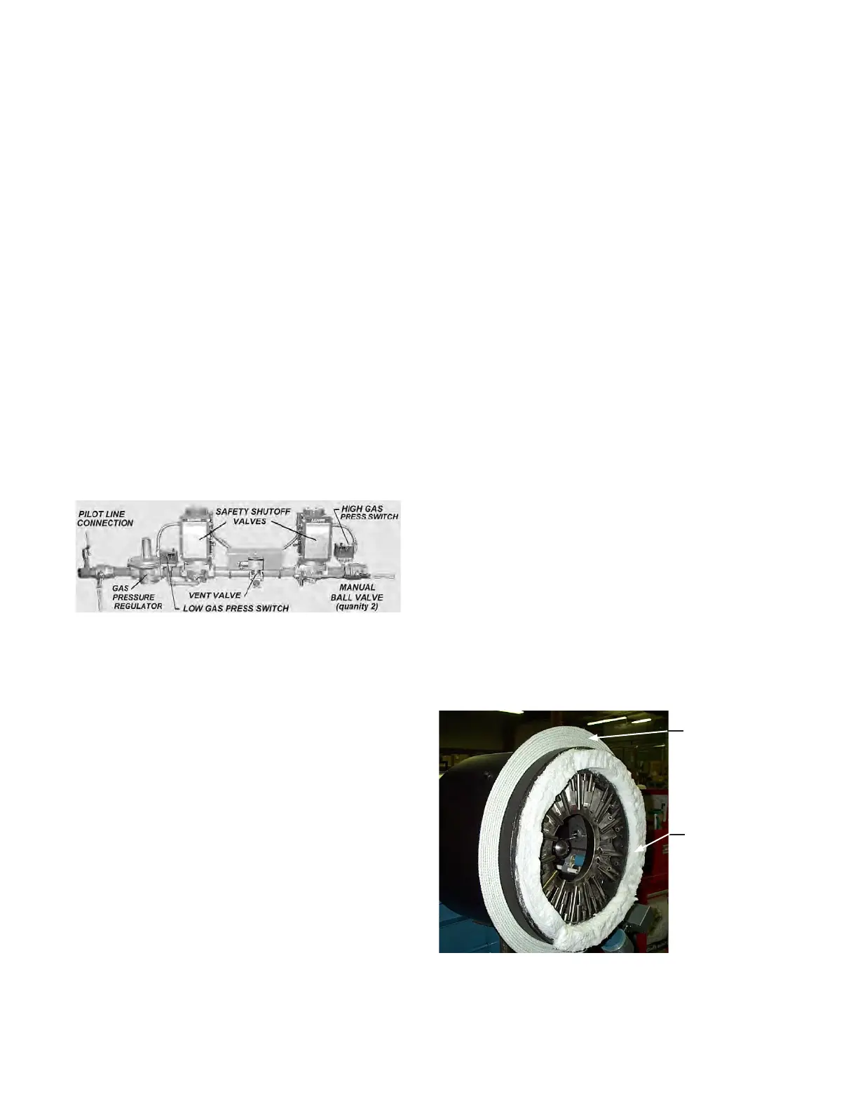
Gas Train
The gas train contains the safety shutoff
valves, manual shut-off valves, pressure
switches and other components that may be
required for the specic installation, available
Figure B-10 Typical Gas Train
gas pressure, insurance codes and local regulations.
The details of the gas train can vary greatly from
burner to burner. Gas trains are typically designed for
each application and a specic gas train assembly
drawing is provided for each unit, identifying the
major components. Details are provided in the
manual included with each burner.
The gas train shown in Figure B-10 uses a gas
pressure regulator upstream of two safety shutoff
valves. Another common style is to have the gas
pressure regulation built into the second safety
shutoff valve.
Gas Safety Shutoff Valve
Each gas train has two shutoff valves in the gas train.
These shutoff valves are usually motorized to open
and spring return to close. They may contain a proof
of closure switch to prove that the valve is in the
closed position prior to starting the burner.
High Gas Pressure Switch
This switch is located after the last shutoff valve
and before the gas ow control valve. It is set at a
pressure that is greater than the highest gas pressure
expected at this location. If the gas pressure rises
above this level, it will trip the switch and cause the burner
to shut down.
Low Gas Pressure Switch
This switch is located before the rst shutoff valve. It is set
to a pressure that is below the expected gas pressure at
this location. If the gas pressure falls below this setting, the
switch will trip and cause the burner to shut down.
Gas Pressure Regulator
Each gas train must have a gas pressure regulator. The
regulator insures a consistent supply pressure to the
burner. Often, the gas pressure regulator is the rst item
in the gas train, or it can be integrated into the second
shutoff valve.
Gas Control Valve
The gas control valve is used to modulate the ow of gas
fuel to the burner. On a single point positioning system
(linkage), it is connected to the jackshaft and uses a fuel
cam to make ne adjustments to fuel ow. When high
turndown is used with linkage, a gas valve with mechanical
stops and overtravel linkage is used to lock in low re. With
a parallel positioning system (linkageless), an actuator
is connected to the gas control valve, and modulated by
electronic control to the desired position. The gas control
valve is located on the pipe that connects to the manifold.
Gas Manifold
The gas manifold (gure B-11) is a cylindrical chamber that
has radial gas ports used to direct the gas fuel. Gas spuds
are installed in these radial ports to improve the distribution
of the gas. The gas manifold also holds the diffuser end of
the burner drawer, which ts tightly into the gas manifold.
This centers the diffuser in the gas manifold, which is
required to obtain good mixing of the gas and air.
The face of the gas manifold is protected from the high
ame temperatures by a refractory front plate, which is
designed to withstand high temperatures. In addition, a
ceramic blanket is used between the face of the manifold
and the refractory to slowdown the transfer of heat.
Rope Gasket
Ceramic Blanket
Figure B-11 Gas Manifold
Mounting Flange
The primary support for the burner is the mounting ange
on the gas manifold. This provides a clamping surface to
 Loading...
