resonance. The size should be based on a maximum
velocity of 30 ft/sec. Changes in direction must be as
slow as possible. Circular elbows should be of at least a
four piece construction with a centerline radius that is at
least double the duct diameter (use three times the duct
width for square ducts). The breeching should have a
slight upward elevation (about 1” per foot) towards the
stack to help induce a draft. Figure C-15 shows the total
BHP that can be red within different breeching diam-
eters. These can be multiple boilers of different size.
CAUTION
OIL BURNING EQUIPMENT SHALL BE
CONNECTED TO FLUES HAVING SUFFICIENT
DRAFT AT ALL TIMES, TO ASSURE SAFE AND
PROPER OPERATION OF THE BURNER.
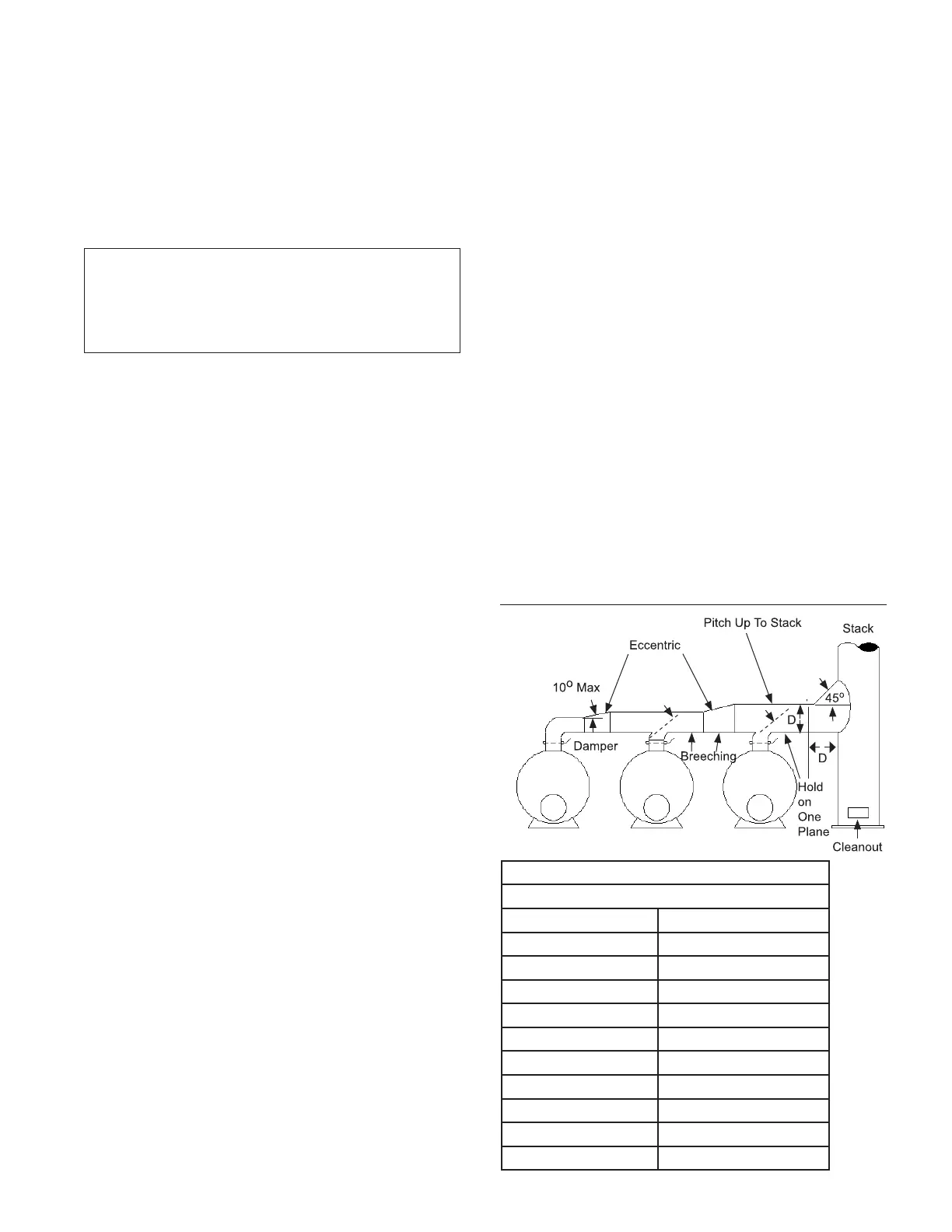
The connection of the breeching to the stack, or
multiple boilers to a common breeching or stack, must
be done with care. The ducts should never be
connected at a 90º angle, but at a 45º angle where the
ows will easily join each other. When connecting
multiple boilers to a single breeching, the breeching
size must be increased to accommodate the larger
ow rates before the added ow is introduced. These
size changes must be gradual, with no more then a 10º
slope change in the duct. When multiple breechings are
connected into a common stack, their locations must be
staggered to prevent the ow of one breeching interfer-
ing with another. Figure C-14 shows these guidelines.
Tall stacks can generate large drafts, and in fact the
amount of the draft is related to the stack height.
Systems with multiple boilers can have draft variations
that are well beyond the desired level. These conditions
must be corrected to allow the burner to work properly,
or the draft variations will cause combustion problems.
Controls can be added to compensate for this draft,
and bring it back to the desired level. The baromet-
ric damper is the most common and least expensive
control. Several barometric dampers can be added to
provide the total correction to the system draft.
Draft controls are also available to regulate the draft by
controlling an outlet damper. The speed of response is
critical to allow these units to work correctly. If the draft
control does not operate faster than the burner changes
rate, the result may be large swings in draft as the
control attempts to catch up with the burner. A feed for-
ward control is the best means of achieving this. If there
are large drafts due to tall buildings, special
consideration must be given to the type of damper
needed to regulate this draft, and the response of the
control to maintain the proper draft.
11. Electrical System
The burner is supplied as standard, with a control panel.
The panel can be integral to the burner or remote for
oor or wall mounting. The proper location will allow the
operator to see the burner operate while manning the
controls. In some areas, there are local regulations that
dene where the control panel must be mounted
The remote control panel must be securely attached to
either the oor or the wall. This should include lag bolts.
The wiring diagram for the specic job should be
followed for connections to the panels and external
equipment. The National Electric Code, Canadian
Electrical Code, Part 1 or similar code for other
jurisdictions should be followed.
The following list covers the standard acronyms:
AUX. – Auxiliary
CB – Circuit Breaker
C.C.W. – Counter Clock-Wise
C.W. – Clock-Wise
CR( ) – Control Relay
FGR – Flue Gas Recirculation
FTS – Fuel Transfer Switch
GND – Ground terminal
H.W.C.O. – High Water Cut Off
INT – Interlock
L – 120V line
L.F.H. – Low Fire Hold switch
L.W.C.O. – Low Water Cut Off
MR – Manual Reset
N. – 120 V Neutral
N.C. – Normally Closed
N.O. – Normally Open
P.L.F.S. – Proven Low Fire Start
P.O.C.S. – Proof Of Closure Switch
SW. – Switch
TDR – Time Delay Relay
JBE(X) Manual
Section C - Installation
Page 27
45
o
o
Figure C14 - Method
of Connecting
Breechings and
Stacks
Figure C-15
Maximum Boiler HP in Breeching
Breeching Dia. (in) Total Max Boiler HP
16 200
18 300
20 400
22 500
24 700
26 900
28 1100
30 1400
32 1600
34 1900
 Loading...
