5. General Oil Piping
WARNING
DO NOT USE TEFLON TAPE OR COMPOUNDS
CONTAINING TEFLON. THIS COULD DAMAGE THE
VALVES CREATING AN UNSAFE OPERATION.
The amount of oil piping required in the eld will depend
on the type of system and how the burner was pur-
chased. If the burner was factory mounted to the boiler,
much of the installation work may already be complete.
Units with heavy oil are more complex and will require
more installation. The items identied in this manual as-
sume that none of the installation work has been done.
The oil piping must be constructed to provide the ow
and maintain the pressure required for proper system
operation. Refer to the previous section for details on
each of the different oil systems and how they operate.
See Figure C-4 for typical oil piping system.
Some actions required for successful piping are:
a. Oil storage tanks and piping must conform to the
National Fire Protection Association “Standard for
the Installation of Oil Burning Equipment NFPA-31”,
local ordinances and EPA underground storage tank
requirements.
b. Oil lines shall be supported and protected against
physical damage. Buried lines shall also be
protected against corrosion.
c. After installation and before covering, buried lines
should be pressure tested for leakage.
d. Cast iron ttings should not be used.
e. Aluminum tubing should not be used.
f. Proper allowance should be made for expansion and
contraction, jarring, vibration and tank settling.
g. Always run full size lines. Fig. C-8 gives pipe sizes.
h. Suction and return lines shall be as short as possible.
i. Oil lines must be cleaned to remove water, rust and
foreign matter. A common method of cleaning the
piping is to temporarily install a short copper tube to
the pump inlet, to feed the oil from a bucket. The
gauge must be removed and the tapping plugged.
The pump is run for a short time by manually
engaging the motor starter. If ow does not establish
within 2 minutes of engaging the pump, shut it off and
run through the priming procedure again.
j. The standard oil pumps can provide suction (vacuum)
of 10” of Hg when used to pull from a tank.
k. A strainer is required to protect the pump, valves and
oil nozzle. This strainer is not part of the standard
equipment supplied by Webster, but is intended to be
supplied and installed by others. The strainer should
have a maximum lter opening of 0.027” for #2 oil,
sized to handle the full ow rate of the pump (Figure
C-7). The strainer must also handle the temperature
and pressure. Retain the strainer instructions supplied
by the manufacturer. It is essential that these
instructions be followed to insure proper ltration to
protect the pump, valves and nozzle.
l. In Canada, refer to CSA Standard B139,
“Installation Code for Oil Burning Equipment” for
recommended installation procedures.
m. The oil lines and most valves are sized for full pump
capacity. Pumps are selected for a capacity of at
least 1.5 times the maximum nozzle rate. If pumps
are used with substantially higher ow rates, these
selections may not function correctly. This is critical
for the pressure atomized system where the
metering valve is sized for the pump ow.
The selection of the oil pipe line size is critical for
proper operation of the system.
JBE(X) Manual
Section C- Installation
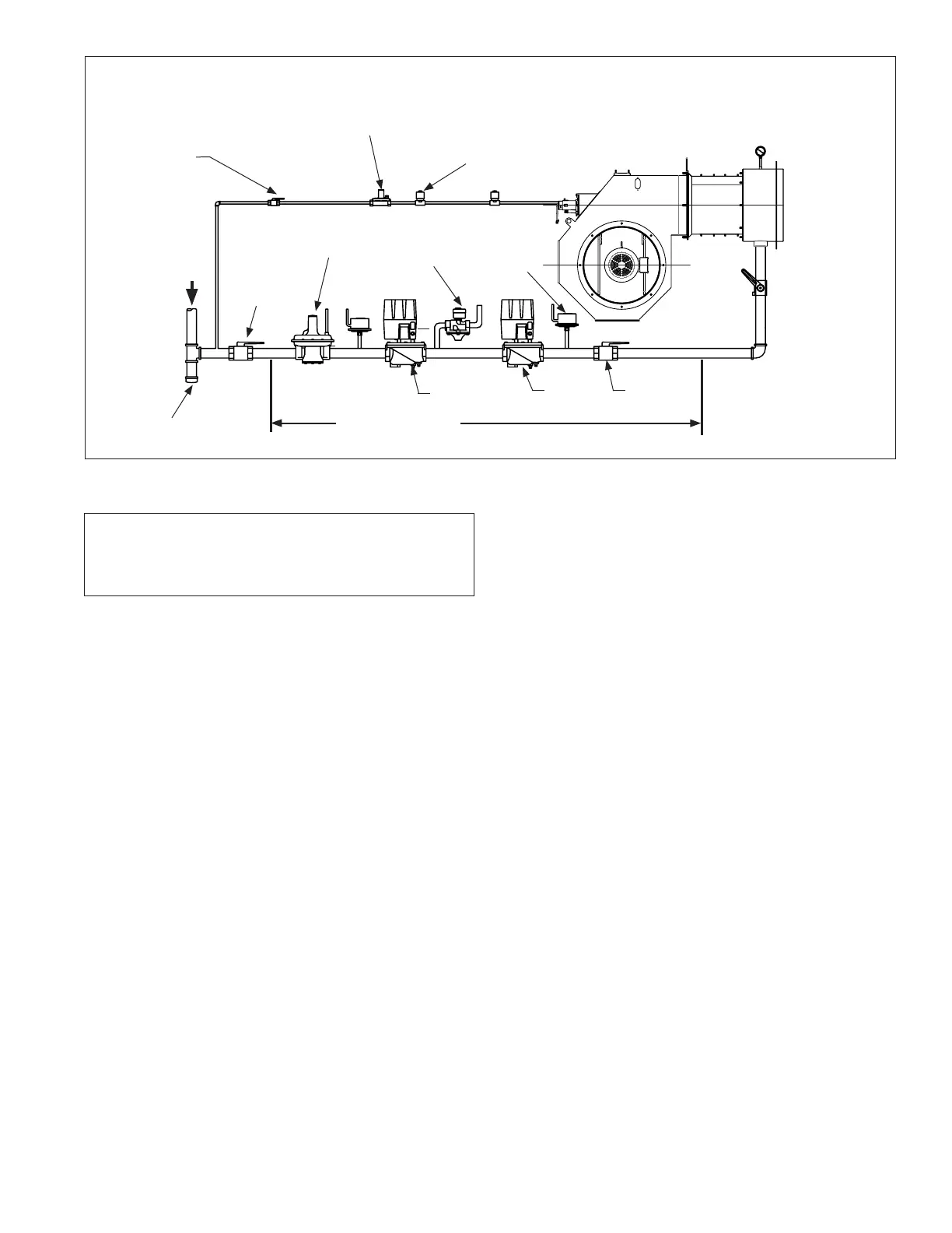
Drip Leg
Manual Gas
Shutoff Valve
Gas Pressure
Regulator
Low Gas
Pressure
Switch
Shutoff
Valve
Shutoff
Valve
High Gas
Pressure
Switch
Normally
open vent
valve
Pilot Gas
Pressure
Regulator
Pilot Solenoid Valve
Pilot
Shutoff
Valve
Figure C-10 Typical Gas Piping
Gas Supply
Burner
Leak Test
Valve
If applicable, Webster
supplied gas train
Page 23
 Loading...
