10. Pressure Atomized Oil Setup
The pressure atomized oil system has a limited range of
adjustment for low and high re, dictated by the operation
of the oil nozzle. The combustion air and FGR must be
adjusted to match these rates.
If the burner is equipped with FGR, and is a linkage sys-
tem, the type of FGR control must be determined prior
to starting. If this is a dual fuel burner, the FGR rate is
determined by the NOx performance on gas. A 60 ppm
burner will operate with the same FGR rate on gas and oil.
A 30 ppm unit will use the limiting potentiometer to slightly
reduce the FGR rate on oil ring. For Oil only combustion,
the NOx level will be given on the burner detail sheet, and
should be used to set the FGR control valve.
a. Place the burner switch in the “OFF” position.
b. Place the “Auto-Manual” switch in the manual position.
If this is a combination fuel burner, make sure the fuel se-
lector switch is on “OIL”.
c. Place the manual ame control potentiometer in the
min (low re) position.
d. Turn the electrical power for the burner, boiler and
related components on.
e. Verify that the oil metering valve is nearly opened (the
valve will be closed at high re).
f. Turn the burner switch on. This will start the blower
motor and initiate the purge cycle.
g. When the prepurge sequence is complete and the low
re start switch is made, the pilot valve will open and the
pilot ame should be visible through the burner sight port.
h. When the pilot ame is established, the ame safe-
guard will energize the main oil valves (indicated with the
Fuel Valve Light), and the burner should ignite at low re.
This operation of the main fuel valves must be visually
checked by observing the valve stem moving up with a
motorized valve or hearing the clicking noise from a sole-
noid valve.
NOTE: If the burner is not operating as indicated, follow
the troubleshooting steps to determine the problem and
corrective action.
i. The main ame may not light on the rst attempt, be-
cause it must ll the oil lines before providing oil to the
nozzle. Press the reset button on the ame safeguard to
restart the burner.
WARNING
DO NOT ATTEMPT TO START THE BURNER WHEN EXCESS OIL
HAS ACCUMULATED, WHEN THE UNIT IS FULL OF VAPOR, OR
WHEN THE COMBUSTION CHAMBER IS HOT.
j. After a few seconds, the combustion analyzer should
have an accurate reading of the O2 in the stack. The O2
level should be between 4% and 8%, and the nozzle oil
pressure should be between 50 and 70 PSIG. Do not at-
tempt to ne tune combustion until the high re has been
set.
If the burner is equipped with FGR, the FGR control valve
should be set for the approximate NOx level required.
1. Turning the cam screw in will add fuel, making it richer
and reducing the O2 level.
2. Turning the cam screw out will reduce the fuel input,
increasing the O2 level.
3. The air damper should be positioned for the correct
low re settings.
k. Operate the burner until the boiler is warmed up, and
near the operating pressure or temperature.
l. Increase the ring rate, using the manual potentiometer,
while monitoring and adjusting the O2 level. Adjust the
cam as needed to reach the high re input.
If the burner is equipped with FGR, adjust the FGR control
valve as required to maintain the NOx level.
m. At high re (end of the modulating motor travel), ad-
just the high re input (open or close the fuel valve) to
match the maximum input listed on the rating label. The
fuel metering valve should be nearly closed (or closed) at
this point and the nozzle pressure should be about 150
PSIG (return line).
n. If equipped with FGR, adjust the NOx level to be about
10% below any guaranteed NOx performance or if perfor-
mance guarantee exists adjust the FGR to provide some
added turbulence but not high enough to impact ame sta-
bility. A balance of the FGR control valve and air damper
are required to obtain the nal result, as each can impact
the other. If this is a 30 ppm system, the FGR limiting pot
should be adjusted to reduce the FGR rate for stable com-
bustion, with the FGR control valve set when ring gas. If
this is a 60 ppm system, no adjustment is necessary.
o. Modulate the burner to low re, adjusting the O2 level
as the burner modulates.
Page 45
Section F - Startup and Operating Instructions
JBE(X) Manual
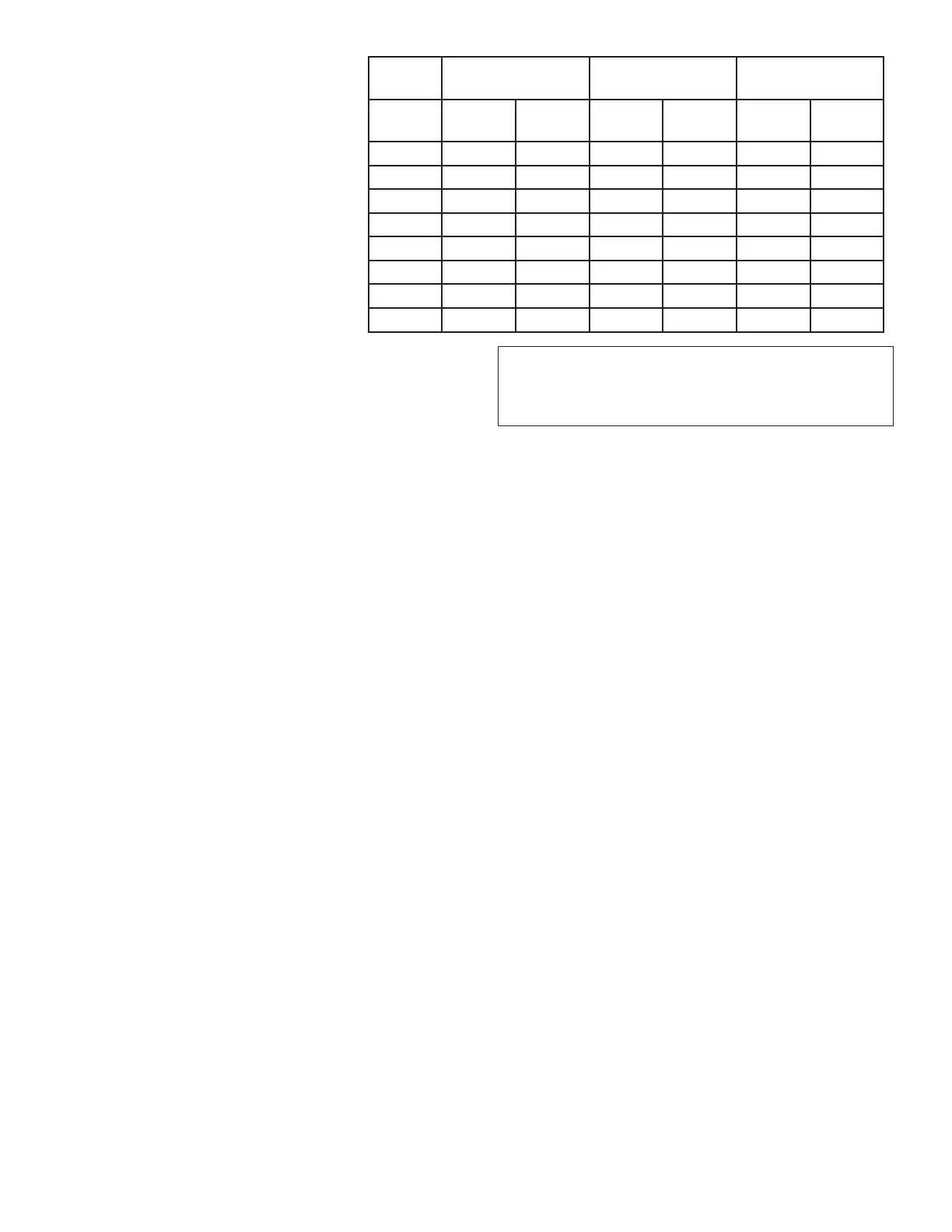
Natural Gas
With FGR
Natural Gas
No FGR
Oil
% Rate Min
% O2
Max
% O2
Min
%O2
Max
%O2
Min
%O2
Max
%O2
8 5.0 9.0 7.0 13 NA NA
10 5.0 9.0 5.5 12 6.0 10.0
15 4.0 8.0 4.5 10 5.0 9.0
20 3.0 8.0 3.5 9 4.0 8.0
30 2.0 7.0 3.0 8 3.5 7.5
40 2.0 7.0 2.5 7 3.0 7.0
50 2.0 6.0 2.5 6 3.0 7.0
100 2.0 6.0 2.5 6 3.0 6.5
Figure F-2
O2 levels
 Loading...
