6
TRANSMITTER
CLEARANCES & FIXING
FITTING & OPERATING INSTRUCTIONS
8-716-107-486d (12.06)
6mm
E
D
F
INSTALLATION &
COMMISSIONING
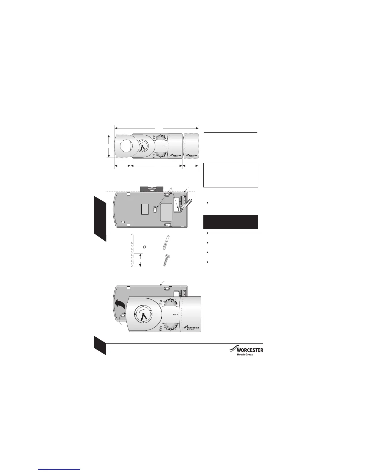
TRANSMITTER CLEARANCES:
See diagram opposite for minimum area
(shown in mm) required for operation.
TRANSMITTER
CLEARANCES & FIXING
TRANSMITTER FIXING:
Hold baseplate (B) level to mark
securing points (C) and remove
baseplate (B).
%
Drill holes, where marked, 30mm
deep using a 6mm diameter drill bit.
&
Push one wall plug (D) into each
hole.
'
Reposition baseplate (B), check
level and secure with screws (E).
(
Align outer edge and internal lugs
(F) of transmitter to baseplate (B)
and push fit to secure.
CAUTION: Ensure there are no
pipes, electric cables or other
hazards before drilling.
B
SAFETY: All relevant safety
precautions must be undertaken.
Protective clothing, footwear,
gloves and safety goggles must
be worn as appropriate.
C
B
1
2
3
4
5
45
250
45 160
75
30mm

 Loading...