Alto Hardware Manual Section
2:
Microprocessor
10
controlled
by
the relevant words
of
page 1 in its bank.
Programs
which
use the extended memory must
fIrst
initialize it to have correct parity. This involves
disabling parity interrupts, storing something in
every
word, flushing any parity interrupts that result, and
then reenabling parity interrupts. The standard bootstrap loaders initialize bank zero only.
All
Alto lIs manufactured starting with the 7
th
build have the extended memory option but are normally
shipped with memory chips for bank zero only. Some earlier Alto lIs have been
modifIed in the fIeld.
Machines
with
the extended memory option have engineering number 3
--
see the description
of
the
VERS
instruction.
2.4 Microprocessor Control
Control
of
the Alto microprocessor
is
shared among
16
"tasks" arranged
in
a priority order. The tasks
are numbered
0 to
15:
0
is
the lowest priority task and
15
is
the highest.
The
lowest priority task
is
the
emulator
task
which fetches instructions and executes them.
The only state saved for each task
is
a "micro program counter,"
MPC.
The
current task number, saved
in the current task register, addresses a
16
by
12
MPC
RAM.
The result
is
an
MPC
for the current task;
it
is
used to address a lK by 32-bit read-only microinstruction memory
(MI
ROMO)
or
a 1K by 32-bit
writeable microinstruction memory
(MI
RAMO),
described in section
8.
An
optional feature
of
Alto lIs
extends the
MI
ROM
to
2K
or the
RAM
to
3K
--
see section
8.
BRANCHING
The microprocessor offers a limited branching capability
which,
although somewhat cumbersome, has
proven adequate for chores undertaken
by
Alto microcode. The basic idea
is
that special microprocessor
functions
may.
modify the
NEXT
fIeld,
and consequently alter the flow
Of
control. Modification
is
accomplished
by
DRing
various bits into the
NEXT
field.
Address modification
is
complicated slightly because the Alto pre-fetches one microinstruction ahead.
Consequently,
a branch condition modifies
the
NEXT
field
of
the microinstruction following the
one
in
which
the
condition
test
is
placed.
This property
i~~
best" illustrated
...
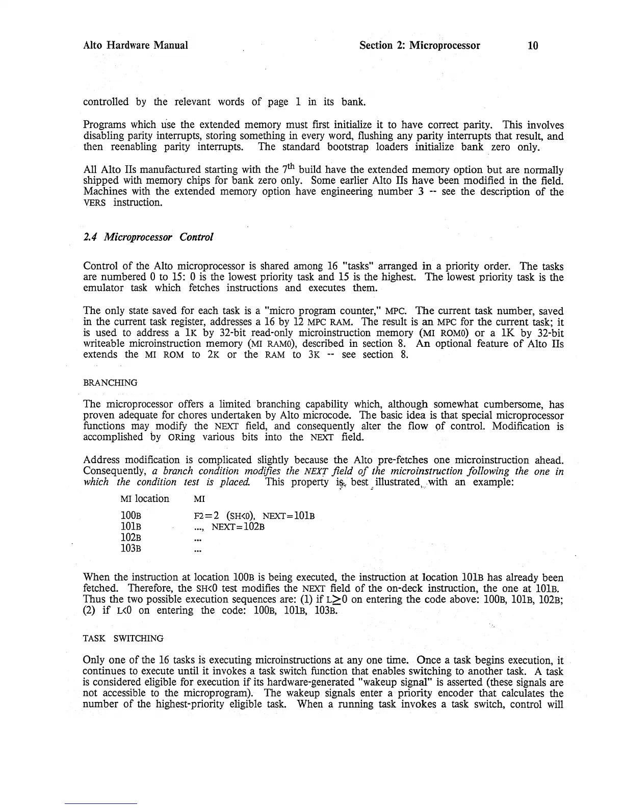
with an example:
MI
location
MI
100B
10lB
102B
103B
F2=2
(SH<O).
NEXT=101B
...
,
NEXT
=
102B
When the instruction at location
100B
is
being executed, the instruction
at
location
101B
has already been
fetched. Therefore, the
SH<O
test modifies the
NEXT
field
of
the on-deck instruction, the one at 10lB.
Thus the
two
possible execution sequences are:
(1)
if
L>O on entering the code above:
100B, 100B,
102B;
(2)
if
L<O
on entering the code:
100B,
10lB,
103B.
TASK
SWITCHING
Only one
of
the
16
tasks
is
executing microinstructions
at
anyone
time. Once a task begins execution, it
continues
to
execute until it invokes a
task
switch function that enables switching to another task. A task
is
considered eligible for execution
if
its hardware-generated "wakeup signal"
is
asserted (these signals are
not accessible
to
the microprogram). The wakeup signals enter a' priority encoder that calculates the
number
of
the highest-priority eligible
task.
When a running task invokes a task switch, control
will
 Loading...